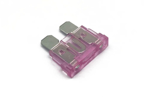
50A fuse is a core component designed for circuit protection, widely used in the electrical system of automobiles, construction machinery and other equipment, which can effectively prevent damage caused by circuit overload and short circuit.
Product Characteristics and Parameters
1. Electrical parameters
Rated current: 50A (Ampere)
Operating voltage: low voltage applicable (specific voltage range can be customized according to actual demand)
2. Physical Characteristics
Structure: Standard plug-in design (supports various specifications)
Fusing Characteristics: Fast blowing type (F type)
Temperature range: -40℃ to 120℃ (operating temperature range)
3. Performance Characteristics
Adoption of high-quality alloy fusing material
Precise fusing characteristic curve
Stable electrical performance
Resistant to vibration and shock
50 Amp Fuse Function
A 50 Amp (50A) fuse is a critical circuit protection component that is primarily used to prevent damage to electrical systems and equipment caused by current overloads and short circuits, as well as to safeguard usage. Its main functions include:
- Overload protection
When the current in the circuit exceeds the rated value of 50 amperes, the fuse will blow quickly, cutting off the current path and avoiding the risk of overheating of wires, damage to equipment or even fire due to overloading.
- Short circuit protection
In the event of a short-circuit fault, the short-circuit current may surge instantaneously, far exceeding the normal load current. 50A fuse can be blown in a very short time, effectively preventing the short-circuit current from impacting on the circuit and equipment, and reducing the risk of fire.
- Personal safety protection
By cutting off the abnormal current in time, the fuse can reduce the safety risk of electric shock and electric shock caused by circuit failure, providing additional protection for operators and equipment.
- Circuit Stability Maintenance
The fast response of the fuse can effectively suppress current fluctuation, prevent overload or short circuit from affecting the normal operation of other related equipment, and ensure the stability and reliability of the entire electrical system.
Principle of operation
1. Basic Structure Composition
The 50 ampere fuse is mainly composed of the following two parts:
- Conductor part: made of highly conductive metal materials (such as copper, silver or its alloy) to ensure low impedance characteristics under normal operating current
- Protective casing: Usually made of high-temperature resistant ceramic or glass, with the following functions
- Provide mechanical protection
- Prevent the spread of electric arcs
- Insulate from external environmental influences
2. Normal working conditions
When working within the rated current (50A):
- Joule heat generated by the conductor (I²R) is effectively dissipated through the housing
- The overall temperature is maintained within safe limits (typically below 80°C).
- The conductor remains fully energized, and the circuit operates normally.
3. Overload protection mechanism
When the current exceeds the rated value:
- The increase in current results in a square-fold increase in heat generation (Q=I²Rt).
- Conductor temperature rises rapidly
- The melting point of the conductor material is reached (copper: 1083°C, silver: 961°C).
- Specific alloy formulations ensure precise fusing characteristics
- Circuit break protection:
- Conductor vaporization to form a circuit breaker gap
- Simultaneously, the housing effectively curbs any arcing that may occur.
4. Short-circuit protection characteristics
In the face of short-circuit currents (up to thousands of amperes):
- Fusing times can be reduced to milliseconds.
- Enhanced arc extinguishing by special designs (e.g., quartz sand filling).
- Ensure that the fault current is cut off within the first cycle.
5. Key technical parameters
- Fusing curve: under IEC 60269 standards
- Breaking capacity: up to 10kA (depending on the specific model)
- Time-current characteristic: ensures selective protection
This sophisticated protection mechanism allows the 50 amp fuse to differentiate between normal inrush currents and dangerous overcurrents in milliseconds, providing reliable protection for electrical systems.
Fuse voltage tolerance
1. Basic Concepts of Voltage Ratings
The voltage rating (Un) of a 50-ampere fuse is the highest circuit voltage at which it can operate safely and reliably. This parameter is critical because:
- voltage rating directly affects insulation performance
- exceeding the rated voltage may result in:
- Risk of insulation breakdown
- Continued arcing during fusing
- Failure of protection
2. Typical Voltage Classification
- Low-voltage type (32V DC) Main applications: Automotive electrical systems.
- Main applications: Automotive electrical systems
- Common types:
- Plug-in type (ATO/ATC)
- Miniature glass tube (10 x 38mm)
- Features:
- Designed for 12V/24V vehicles.
- Vibration-resistant construction
- Medium Voltage Type (125V AC/DC)
- Main applications:
- Construction machinery
- Industrial equipment
- Common types:
- Fork-bolt type (MEGA/J-CASE)
- Bolt-on type
- Features:
- Higher breaking capacity
- Enhanced arc extinguishing design
3. Key Selection Parameters Comparison Table
| Parameters | Low Voltage(32V) | Medium Voltage(125V) |
|---|
| Typical Applications | Automotive Circuits | Industrial Equipment |
| Overall Dimensions | Compact | Large |
| Breaking capacity | 1kA | 10kA |
| Operating Temperature | -40~85℃ | -40~125℃ |
| Approvals | SAE J554 |
4. Precautions for use
- Principle of voltage matching
- It must be ensured that the circuit operating voltage ≤ fuse rated voltage
- DC rating should be paid special attention to DC system.
- Special Considerations: Transient voltage peaks should not exceed the rated voltage.
- The peak transient voltage should not exceed 120% of the rated voltage.
- Derating should be considered for altitudes over 2000m
- Safety margin recommendation
- Conventional applications: retain 20% voltage margin
- Harsh environment: keep more than 30% margin.
5. Clarification of Common Misconceptions
- Misconceptions about the current/voltage relationship. Misconception: “50A” is a good choice for the current/voltage relationship.
- Misconception: “A 50A fuse can be used for any voltage.”
- Fact: Current rating and voltage rating are independent of each other and need to be satisfied at the same time.
- AC/DC applicability: Most automotive fuses are labeled for D only.
- Most automotive fuses are labeled with DC ratings only.
- Most automotive fuses are only labeled with DC ratings.
It is recommended to always refer to the detailed specifications provided by the manufacturer for actual selection, especially for special application scenarios (e.g., electric vehicles, photovoltaic systems, etc.), which may require customized high-voltage solutions.
50A Fuse Maximum Current
1. Core current parameter description
- Standard value: 50A (nominal operating current)
- Definition: Maximum continuous current that can work stably for a long period under standard test conditions
- Test conditions:
- Ambient temperature 23±5°C
- At rated voltage
- Natural convection cooling
- 2. Actual operating current range
- Recommended operating current: ≤80% In (i.e. 40A)
- Critical operating area: 80-100% In (subject to derating factor)
2. Overload Characterization
| Overload Ratio | Typical Fusing Time | Allowable Frequency |
|---|
| 110% In | >4 hours | Occasionally |
| 135% In | <1 hr | Emergency |
| 200% In | <30 seconds | Fault only |
Note: Refer to IEC 60269 time-current curves for specific data.
3. Special Type Differences
- Conventional blown fuses
- Strict limitation: Continuous current must not exceed 50A
- Instantaneous withstand: 200% of inrush current for <100ms
- Periodic resettable fuse (PPTC)
- Operating limit: 50A (steady state)
- Trip current: usually 200-300% of rated value
- Reset Characteristics: Automatic recovery after troubleshooting
4. Key influencing factors
- Ambient Temperature Correction Factor Ambient Temperature Current Correction Factor 25℃ 1.0 50 ℃ 0.85 70 ℃ 0.75
- Influence of installation method
- Confined space requires an additional 15-20% derating.
- Parallel use requires professional design (not recommended for parallel use)
5. Suggestions for Selection
- Industrial applications **It is recommended to choose IEC standard products.
- It is recommended to choose IEC standard products.
- Focus on breaking capacity (at least 10kA)
- **Automotive electronics
- Prefer SAE-certified products
- Attention to vibration resistance
- **Special Needs
- High-frequency pulse scenarios: choose gg/gL type
- Motor protection: AM type is more suitable
IMPORTANT NOTE: Any use in excess of the rated current of 50A will significantly shorten the life of the product. In critical operating conditions, it is recommended that a higher specification (e.g. 63A) be used to ensure reliability. A complete durability test must be carried out before actual application.
Precautions for Use (Professional Version)
1. Selection key elements
- Principle of current matching
- Calculation formula: Fuse rated current ≥ 1.25 x maximum continuous current of the circuit
- Special scenarios:
- Motor circuit: consider the starting current (recommended 1.5-2 times the rated current)
- Capacitive loads: add 30% margin
- Voltage rating selection
- Basic requirements: Fuse rated voltage ≥ maximum circuit operating voltage
- DC system special attention:
- DC ratings need to be specified
- Polarity-sensitive fuses need to be installed correctly.
2. Performance Parameter Considerations
- Breaking capacity classification | Application Scenarios | Minimum Breaking Capability Application Scenarios Minimum Breaking Capacity Requirements Automotive Electronics 1kA Industrial Controls 10kA Photovoltaic Systems
- Fusing Characteristics Selection Guidelines
- Fast Fusing (FF):
- Application: semiconductor device protection
- Characteristics: ≤0.1s fuse at 200% overload
- Slow fusing type (TT):
- Applicable: Motor circuit
- Characteristics: Can withstand 5-7 times In for 1 second.
3. Environmental adaptability requirements
- Temperature Compensation Coefficients Table Ambient Temperature Current Carrying Capacity Correction ≤25℃ 100% 50 ℃ 85% 70 ℃ 70%
- **Special Environmental Countermeasures
- Vibration: Select spring-loaded mounting
- Humid environment: Select sealed products (IP67).
4. Installation Specifications
- Standard Operating Procedure 1.
- Power off and check the power (use a multimeter to confirm)
- Remove the oxidized layer on the contact surface.
- Use a torque wrench to install (reference value: 2.5 N-m)
- Conductivity test
- Prohibited items
- Prohibit the use of copper wire across the connection.
- Prohibit mixing of different specifications.
- Do not modify the mounting bracket without authorization.
5. Maintenance Management
- Troubleshooting Procedure
- First fuse: Replace with a new product of the same specification.
- Second fuse: check load current (use clamp meter)
- Third fuse: System-level troubleshooting
- Routine inspection cycle: 6 months/times
- Mandatory replacement cycle: 5 years or after 3 fuses
6. Certification Requirements
- Industry Certification Standards Comparison
| Certification System | Key Test Items | Special Requirements |
|---|
| UL248 | Overload/Short Circuit Test | 100% Rated Current Aging Test |
| Breaking Capacity Test | 5,000 Mechanical Endurance Cycles |
| IEC 60269 | Time-Current Characterization | Environmental Temperature Cycling Test |
| Arc Energy Test | Durability Test (1,000 hours) |
| GB/T 13539 | Temperature Rise Test | Salt Spray Test (96 hours) |
| Overload/Short Circuit Test | Vibration Resistance Test |
Important: When using 50A fuses in new energy vehicles (EV) or photovoltaic systems, it is important to select products with appropriate DC voltage approvals (e.g., UL2750) and to consider arc suppression design. It is recommended that a fuse replacement log file be established to track the root cause of each blowing event.
Fuses are widely used in various circuits to protect electrical equipment from overloads and short circuits. Choosing the right fuse needs to be based on the rated current, voltage, and melting time of the circuit. The rated current is the value of the current that the fuse can continuously pass, and the fuse will blow if it exceeds this value; the voltage should generally be less than or equal to the operating voltage of the circuit; the melting time refers to the time from the current exceeding the rated value to the melting time, which is usually determined by the material and design parameters of the fuse. In addition, there are some special types of fuses, such as fast blow fuses and delayed blow fuses, which are used to respond quickly to overload conditions and to allow current to pass for a while under brief overload conditions, respectively.
50 Amp Fuse FAQs
Q1: Why does the fuse blow so often when I use the air conditioner in my house?
A: This is a typical overload problem. When using multiple high-power appliances at the same time (e.g., air conditioner + heater), the total current may exceed 50A. suggestions:
- Calculate the total power of all electrical appliances (1P air conditioner ≈ 8A, electric heater ≈ 10A)
- Staggered use of high-power appliances
- If you need to use high load for a long time, we suggest you to upgrade the circuit instead of just replacing the fuse with a bigger one.
Q2: What should I do if the fuse blows occasionally when the equipment starts up?
A: This is caused by pulse current shock. The following measures are recommended:
- Replace the fuse with a slow-blowing fuse (model number with “T” mark)
- Check whether the starting current of the equipment is abnormal
- Ensure that the fuse is securely installed (recommended torque 2- 3 N-m)
- Consider installing a soft start device.
Q3: What are the signs of poor fuse contact? How to solve it?
A: Common symptoms include:
- Black discoloration of the fuse holder
- Smell of burnt plastic
- Intermittent power failure
Solution:
- clean contact surfaces after power failure (use fine sandpaper or contact cleaner)
- Check for loose terminals
- Replace badly oxidized fuse holders
- Check contact resistance periodically (annually)
Q4: What are the possible causes of instantaneous fuse blowing?
A: It is most likely a short circuit fault and should be immediately:
- Disconnect all electrical appliances
- Use a multimeter to measure the line resistance (normal should be > 1MΩ)
- Focus on checking:
- Damaged wires
- Water inlet socket
- Short circuit inside the appliance
- Do not replace the fuse until the problem is solved.
Q5: How can I tell if a fuse needs to be replaced?
A: Fuses should be replaced in the following cases:
- It has been in use for more than 5 years (even if it has not blown).
- The surface is oxidized or deformed
- It has been blown more than 3 times
- Measured resistance value exceeds 15% of the new product
It is recommended to set up a replacement record and replace it once every 3-5 years in a normal environment.
Professional Tips: Be sure to disconnect the power before all maintenance operations! If the same problem occurs repeatedly, please consult a professional electrician for a systematic check. Increasing the fuse size arbitrarily may cause the line to overheat and cause a fire.