Hoe reflow solderen op dubbelzijdige PCB?
Inhoudsopgave
Waarom is dubbelzijdig PCB Reflow Solderen een uitdaging bij de productie van elektronica?
In hoogwaardige elektronische producten, zoals smartphones en industriële regelapparaten, dubbelzijdige PCB ontwerpen zijn de standaard geworden. Dubbelzijdig solderen brengt echter twee grote uitdagingen met zich mee:
- Thermisch beheer Complexiteit - Tijdens het solderen aan de tweede zijde wordt de eerste zijde opnieuw verhit, wat kan leiden tot losgeraakte onderdelen of defecte soldeerverbindingen.
- Proces Selectie Dilemma - Soldeerpasta en rode lijm hebben elk hun voor- en nadelen en vereisen een zorgvuldige afweging op basis van de componentenlayout.
Raadpleeg onze procesingenieurs voor oplossingen op maat
Diepgaande vergelijking van twee belangrijke soldeerprocessen
Optie A: dubbelzijdig soldeerpasta-proces (ideaal voor componenten met hoge dichtheid)
Geschikt voor:
- PCB's met BGA's, QFN's of andere precisie-IC's aan beide zijden
- Lichtgewicht onderdelen
Belangrijkste stappen:
- Zijde A: Print soldeerpasta → Plaats componenten → Reflow soldeer (piektemperatuur 245°C)
- Laat afkoelen tot kamertemperatuur en draai dan de printplaat om
- Zijde B: soldeerpasta afdrukken → componenten plaatsen → getrapt temperatuurprofiel gebruiken (piektemperatuur met 5-10°C verlagen)
Voordelen:
- Hoge betrouwbaarheid van soldeerverbindingen
- Geschikt voor geautomatiseerde massaproductie
Risico's:
- Grote onderdelen kunnen loskomen tijdens de tweede reflow
- Nauwkeurige temperatuurregeling is vereist voor solderen aan de tweede zijde
Optie B: Soldeerpasta + roodlijm hybride proces (oplossing voor grote componenten)
Geschikt voor:
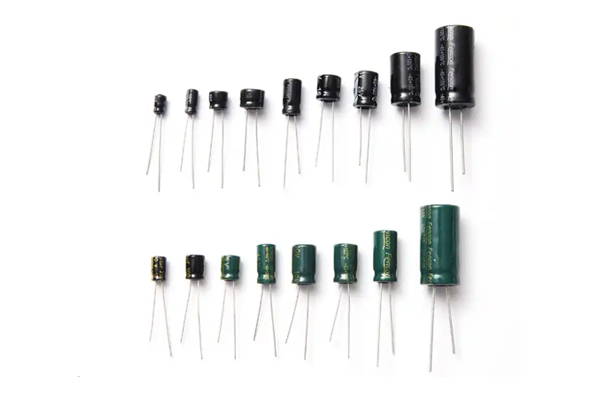
- Eén kant heeft grote connectoren/elektrolytische condensatoren
- Gemengde indelingen met aanzienlijke gewichtsverschillen
Innovatief proces:
- Soldeerpasta-zijde (zijde A): Standaard reflow solderen
- Rode lijmzijde (zijde B): “Print-Place-Cure” driestapsmethode:
- Nauwkeurigheid rode lijm afdrukken: ±0,1mm
- Uithardingstemperatuur: 120-150°C (veel lager dan het smeltpunt van soldeerpasta)
- Optioneel golfsolderen voor verbeterde betrouwbaarheid
Technische opmerkingen:
- Rode lijm moet minstens 0,3 mm verwijderd zijn van de soldeerpads
- Verleng de uithardingstijd met 30% om zwakke hechting te voorkomen
Ontvang gratis handwerkgidsen voor experts
5 gouden regels voor kwaliteitscontrole bij het solderen
- Temperatuurprofiel optimaliseren
- Eerste zijde: Standaard Ramp-Soak-Spike (RSS) curve (2-3°C/s opwarmsnelheid)
- Tweede zijde:Gebruik Ramp-to-Spike (RTS) curve (verlengde voorverwarmingstijd)
- Richtlijnen voor componentlay-out
- Plaats zware onderdelen aan dezelfde kant
- Stagger dubbelzijdige BGA's om thermische spanningsconcentratie te voorkomen
- Soldeerpasta selectiecriteria
- Tweede zijde: Gebruik soldeerpasta voor lage temperaturen (bijvoorbeeld Sn42/Bi58).
- Viscositeit rode lijm:>50.000 cps
- Kritische apparatuurparameters
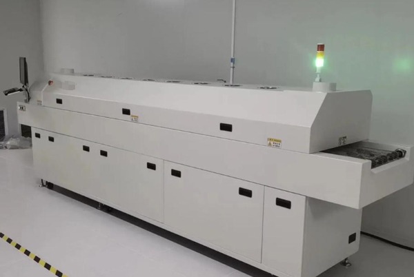
- Kantelen van de Reflow-oventransportband: 5-7°
- Koelsnelheid: 4-6°C/s
- Inspectietechnologie-upgrades
- 3D SPI gebruiken voor inspectie van soldeerpastadikte
- Verplichte akoestische microscopie na de tweede reflow
Veelvoorkomende problemen en technische oplossingen
Probleem 1: verschuiven van QFN-onderdelen tijdens tweede terugvloeiing
- Oplossing: Lijm van hoge temperatuur aanbrengen na solderen aan de eerste zijde
- Parameters:Gebruik lijm met >200°C uithardingstolerantie
Probleem 2: loslaten van onderdelen tijdens golfsolderen (rode lijmzijde)
- Verbeteringen:
- Uitharden met UV na het aanbrengen van rode lijm
- Voorverwarmen tot 100°C voor golfsolderen
Probleem 3: Overmatige voiding in BGA-verbindingen
- Procesoptimalisatie:
- Verleng de ontdooitijd van soldeerpasta tot 8 uur
- Gebruik stikstofondersteunde reflow (O₂ <500ppm)
Toekomstige procestrends
- Solderen bij lage temperatuur: Sn-Bi soldeerlegeringen met gepulseerde verwarming
- Slimme temperatuurregeling: Op machine learning gebaseerde realtime profieloptimalisatie
- Hybride verbinding: Gecombineerde soldeerpasta + geleidende lijmoplossingen
Door deze belangrijke technieken systematisch toe te passen, kunnen technici een first-pass rendement behalen van meer dan 99,5%.We raden aan om procesvenstercontrolesystemen te implementeren voor continue optimalisatie in productieomgevingen.


Verwante berichten