
- точность Решения для печатных плат для применения в условиях повышенного спроса
С 2008 года компания Topfast предоставляет высококачественные услуги по производству и сборке печатных плат по всему миру. Мы предлагаем комплексные решения, начиная с прецизионного производства и заканчивая всесторонним функциональным тестированием, обеспечивая точность и надежность на каждом этапе.
Специализируясь на быстром создании прототипов и оказании услуг по сборке "под ключ", мы используем наш технический опыт и проверенные возможности исполнения для предоставления эффективных, интегрированных и надежных решений для всех ваших потребностей в печатных платах.
- Полный комплекс услуг "под ключ
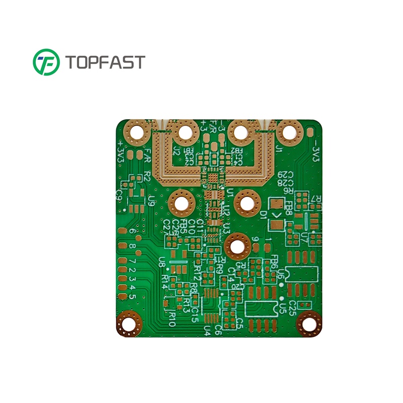
- Изготовление печатных плат премиум-класса
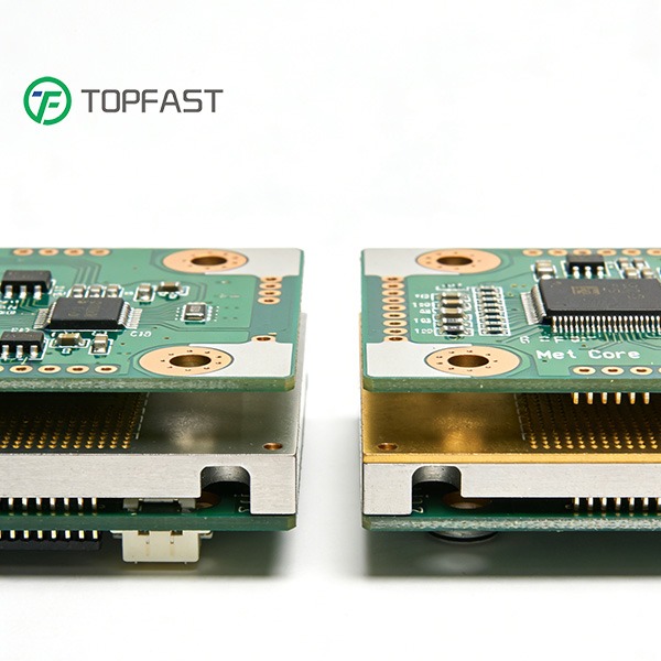
- Надежная сборка SMT
- Аутентичный поиск компонентов
- Строгий контроль качества
Почему стоит выбрать Topfast PCB
Ваш успех от нас Тесное сотрудничество.
Комплексные производственные решения
От быстрого создания прототипов до серийного производства мы обеспечиваем стабильное качество продукции благодаря экспертной поддержке в области технологичности и инженерным консультациям.
Надежный партнер
Наши предприятия, сертифицированные по стандарту ISO, строгие процессы тестирования, конкурентоспособные цены и эффективные циклы поставок гарантируют успех вашего проекта от концепции до выхода на рынок.
0
Ежедневные заказы
0
Завод SQM
0
Глобальные партнеры
0
Технологические патенты
Почему Topfast?
Обслуживание печатных плат/PCBA
Универсальные услуги PCBA
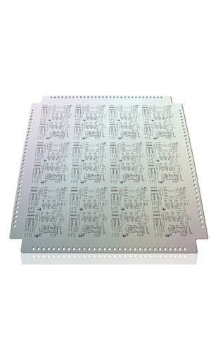
Производство до 64 слоев печатных плат
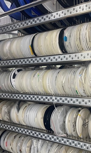
Глобальные закупки запчастей
Оптимизация стоимости BOM
Снижение затрат и повышение эффективности
Быстрый оборот

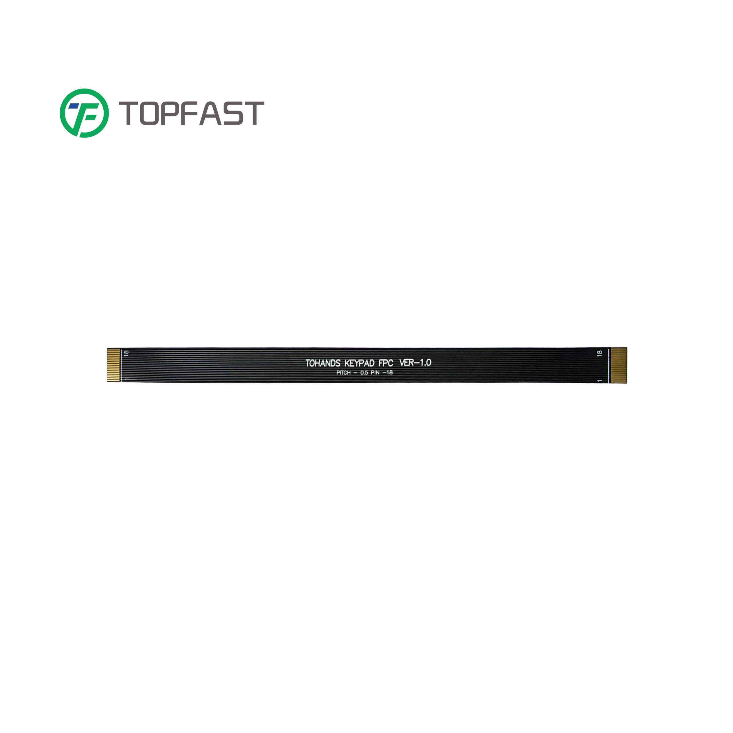
Обслуживание жгутов проводов
Кабельная сборка на заказ
Пользовательские жгуты проводов
Сертифицированный завод ISO площадью 10,000 кв.м.
Высокопроизводительное производство
10+ обслуживаемых отраслей
Профессиональная настройка
Возможности Topfast
Ширина линии/пространство
1.8mil/1.8mil
Слепые и погребенные отверстия
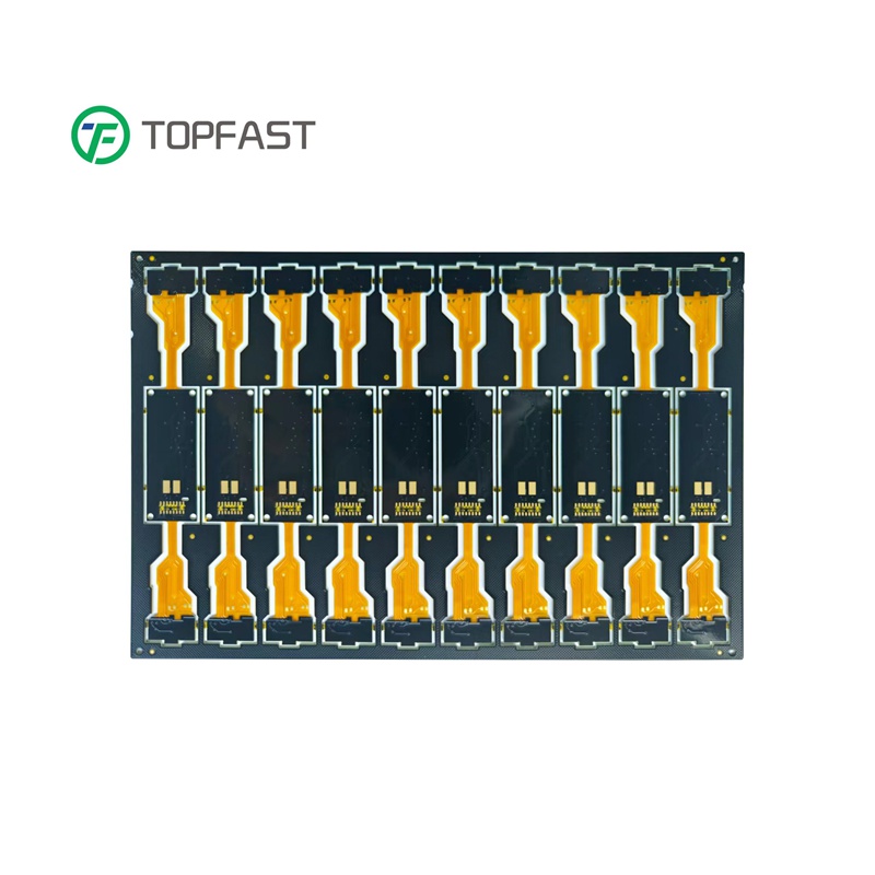
Жесткие, гибкие, жестко-гибкие
Уменьшение размера до 0201
Соответствие RoHS
Толщина от 0,1 мм до 12 мм
IPC A 610H
Контролируемый импеданс
Двухсторонний BGA
Рентгеновский контроль
Бессвинцовые, HASL, OSP и т.д.
Минимальный диаметр отверстия до 0,1 мм
ЧПУ / Металлы
Сборка под ключ
Поиск компонентов


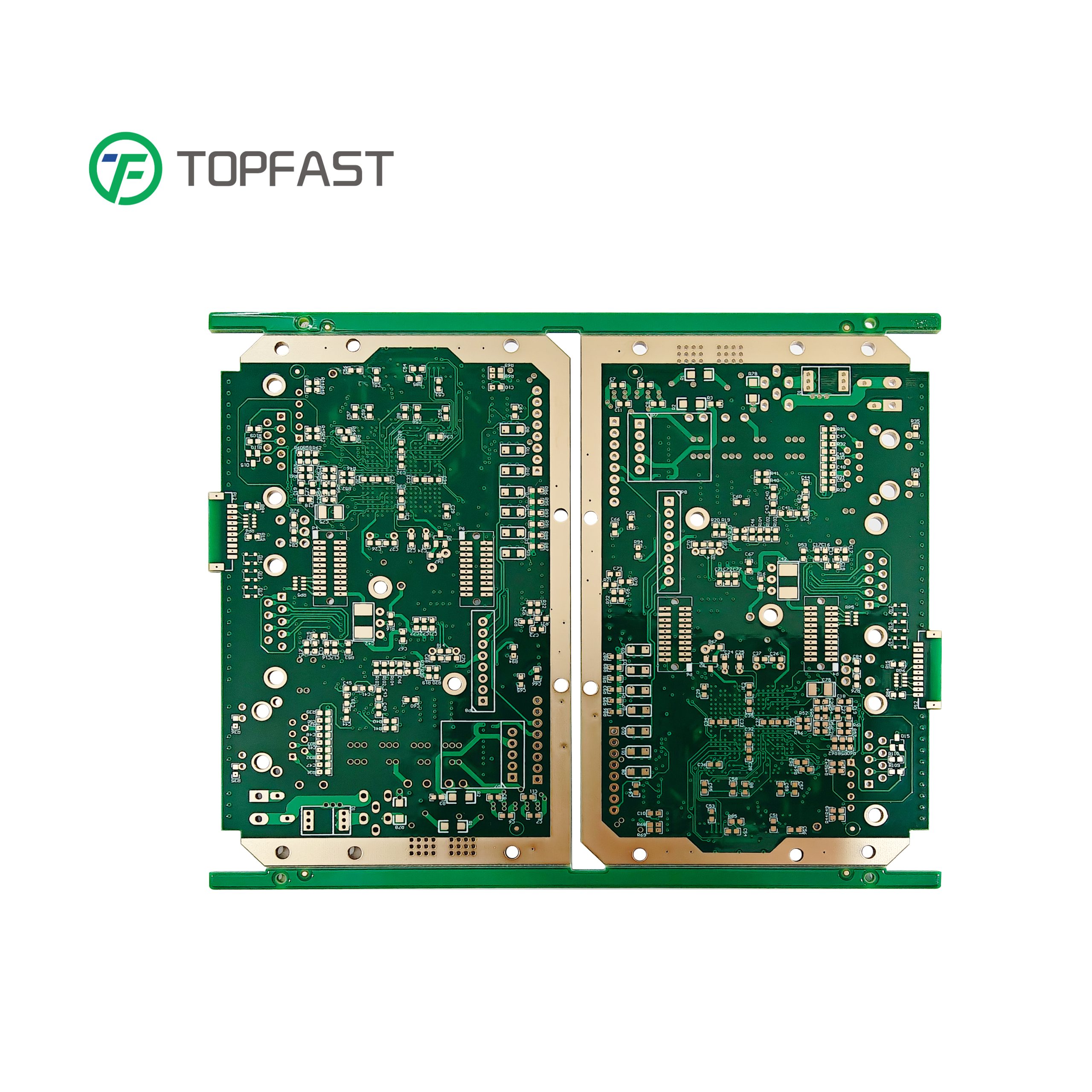
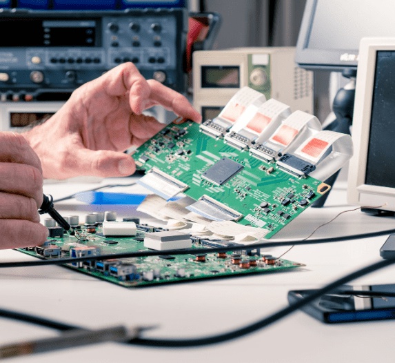
Сборка печатной платы Производитель
Передовые технологии для производства прецизионной электроники
Склад IQC
Входной контроль качества гарантирует соответствие всех компонентов нашим строгим стандартам перед сборкой.
SMD-трафареты
Прецизионные трафареты для точного нанесения паяльной пасты в технологии поверхностного монтажа.
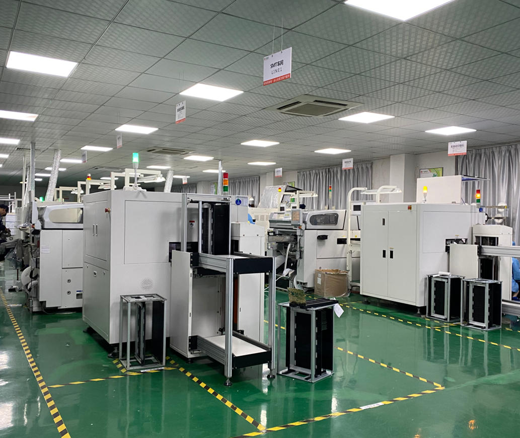
Линия SMT 1 & 2
Современные технологические линии поверхностного монтажа для крупносерийного производства с высокой точностью.
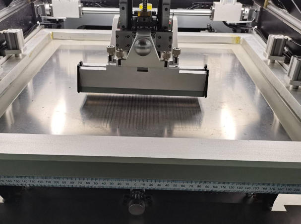
Машина для печати паяльной пасты
Передовая технология печати для точного нанесения паяльной пасты на печатные платы.
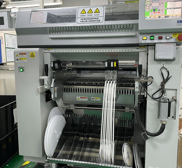
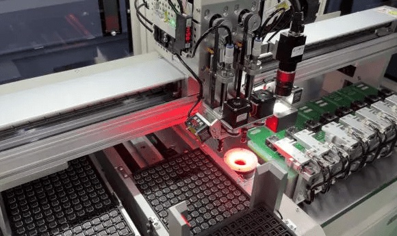
Машина для подбора и размещения оборудования
Высокоскоростная автоматизированная установка компонентов с помощью прецизионной технологии Yamaha.
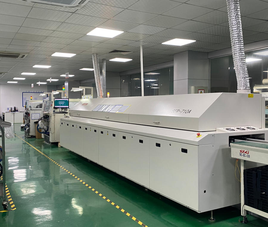
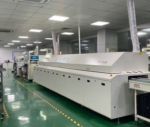
Печь для растапливания
Прецизионное профилирование температуры для идеальной пайки припоя при сборке поверхностного монтажа.
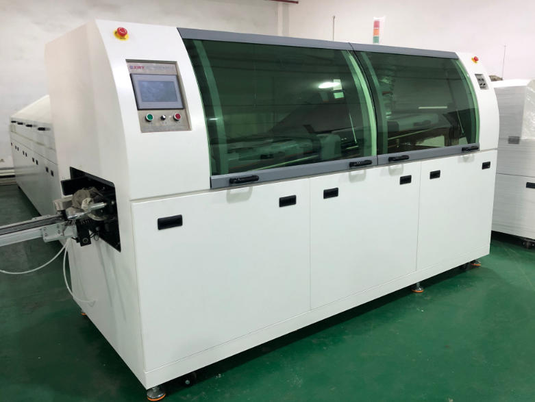
Волновая паяльная машина
Передовая технология пайки волной для сборки компонентов со сквозными отверстиями.
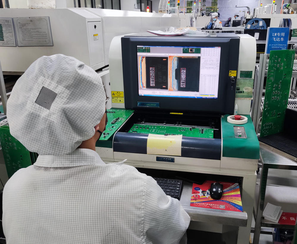
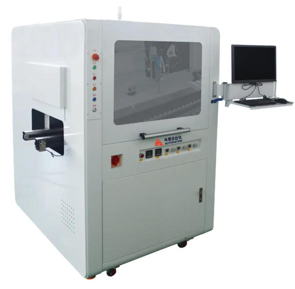
Инспекция AOI
Автоматизированная оптическая инспекция для выявления дефектов сборки и контроля качества.
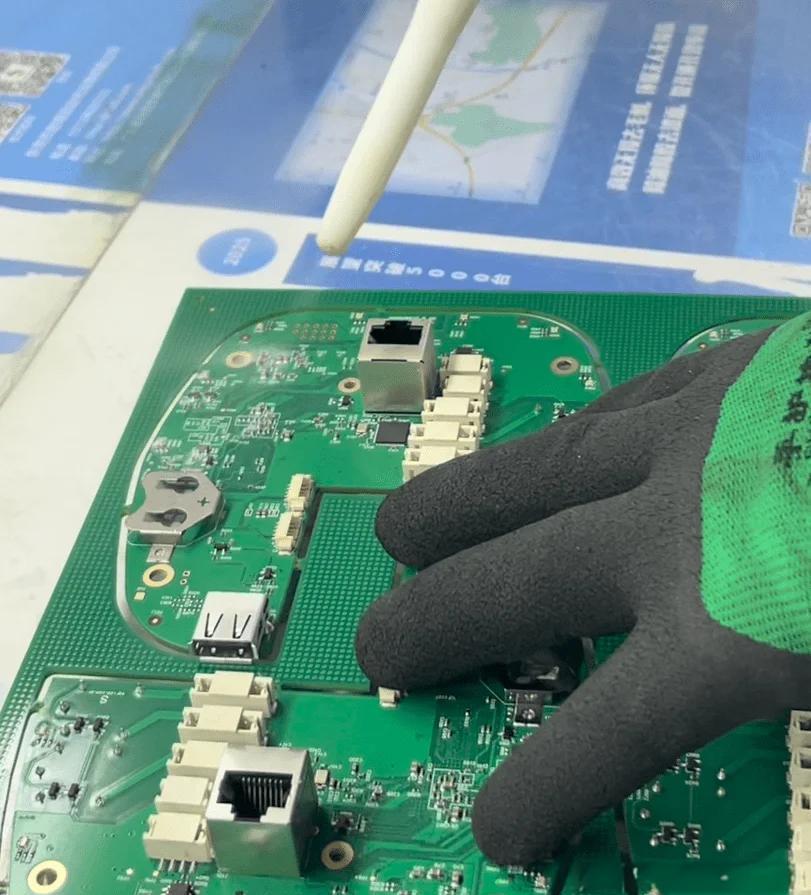
Инспекция контроля качества
Строгий контроль качества гарантирует соответствие каждой печатной платы самым высоким стандартам.
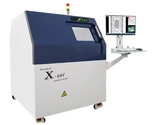
Рентгеновский контроль
Неразрушающий контроль для обнаружения скрытых дефектов в BGA и сложных сборках.
Очистка PCBA сухим льдом
Экологически чистая технология очистки сухим льдом для удаления загрязнений с собранных плат.
Функциональное тестирование PCBA
Всестороннее функциональное тестирование, гарантирующее, что собранные платы работают так, как задумано.
Программирование и тестирование ИС
Программирование и проверка интегральных схем для создания полнофункциональных узлов.
Машина для нанесения конформного покрытия
Автоматизированное нанесение защитных покрытий для повышения долговечности и надежности.
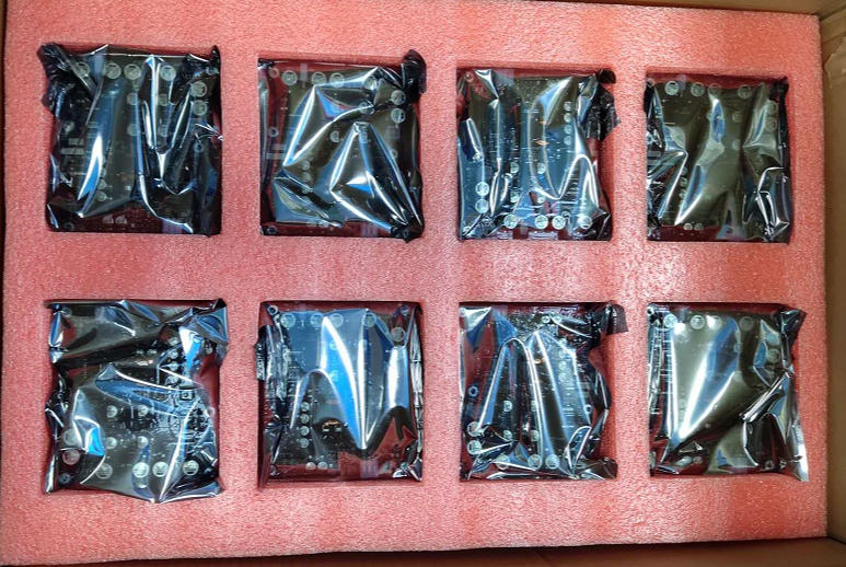
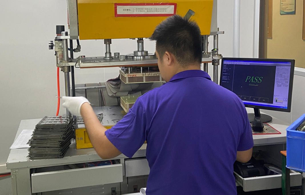
Упаковка PCBA
Надежные и профессиональные упаковочные решения для защиты готовых узлов при транспортировке.
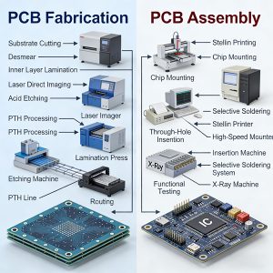
Процесс заказа печатной платы
Услуги по тестированию печатных платМы проводим 100%-ную полную проверку каждой печатной платы. Используя передовые методы, включая тестирование летающим датчиком, автоматическую оптическую инспекцию AOI, рентгеновскую инспекцию, внутрисхемное тестирование ICT и испытательные стойки, мы всесторонне выявляем обрывы, короткие замыкания и проблемы с электрическими характеристиками печатных плат. Используя самые строгие процессы контроля качества, мы гарантируем, что каждый продукт обеспечивает надежное качество и стабильную работу.
Услуги по тестированию PCBA Мы используем высокоскоростные машины YAMAHA и интеллектуальную систему хранения материалов для достижения высокой точности SMT-сборки. На протяжении всего производства современное оборудование, включая SPI, AOI, X-RAY и приспособления для функционального тестирования, полностью обеспечивает качество.
SPI: Автоматически проверяет толщину, площадь и расположение паяльной пасты для повышения качества и эффективности пайки.
AOI: Точное определение состояния пайки компонентов, позиционных отклонений и отсутствующих деталей.
РЕНТГЕН: Выполняет рентгеновский контроль внутренних структур, уделяя особое внимание сложным компонентам, таким как BGA.
Испытательные приспособления: Загрузка встроенного программного обеспечения и команд для всесторонней проверки функциональной надежности PCBA.
Мы неукоснительно выполняем каждый этап технологического процесса, стремясь предоставить нашим клиентам высококачественную продукцию и надежные услуги.
Наши сертификаты
Все наши печатные платы имеют рейтинг IPC и сертификаты UL, ROHS и ISO9001, что гарантирует высочайшие стандарты качества.

Система менеджмента качества
GB/T19001
Автомобильная система качества
Истф 16949
Система менеджмента качества
Стандарт ISO9001
Система экологического менеджмента
Стандарт ISO14001
Сертификация безопасности
UL1. Клиент Отзывы
Узнайте, что говорят наши клиенты о наших услугах и качестве
Связь была бесперебойной на протяжении всего процесса. Команда Topfast была очень отзывчива и внимательна к моим специфическим требованиям. Они терпеливо выслушивали потребности моего проекта, предлагая ценные предложения и рекомендации по оптимизации дизайна и функциональности моих печатных плат.

Интел
Руководитель отдела исследований и разработок
Когда я получил свои печатные платы, я был поражен их качеством. Платы явно были сделаны с точностью и вниманием к деталям, и все было именно так, как я указал в своем заказе. Шелкография была четкой и ясной, все компоненты идеально подошли, и результат превзошел все наши ожидания.

Самсунг
Инженер-электроник
Недавно я имел удовольствие работать с компанией Topfast, ведущим производителем прототипов печатных плат, и должен сказать, что мой опыт был просто выдающимся. От начала и до конца их обслуживание и качество продукции превзошли мои ожидания, и я рад поделиться своим положительным отзывом.

Панасоник
Дизайнер продукции
Ваш надежный производитель печатных плат и поставщик жгутов проводов
Получить цитату
Высококачественное производство печатных плат, сборка и услуги проводки
Быстрое выполнение заказа и надежное обслуживание
