Ремонт печатной платы
Руководство по ремонту плат: от новичков до экспертов
Печатные платы являются ключевым компонентом современной электроники, от смартфонов до промышленных систем управления. Мастерство ремонта плат не только сэкономит вам много денег на ремонте, но и продлит срок службы ваших электронных устройств. Данное руководство содержит исчерпывающую вводную информацию по всем аспектам ремонта плат, включая диагностику общих проблем, выбор инструментов для ремонта, меры безопасности и подробные процедуры ремонта.
Ii. Содержание
Основы работы плат
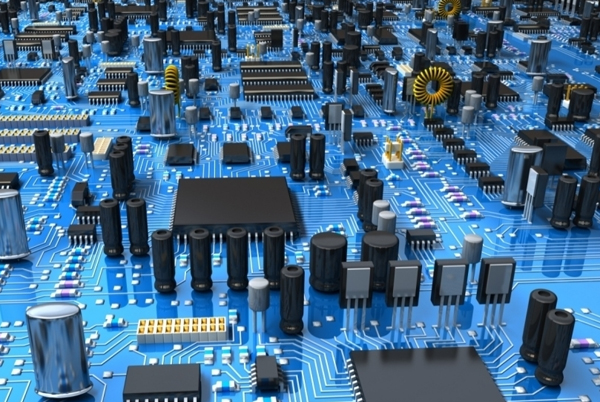
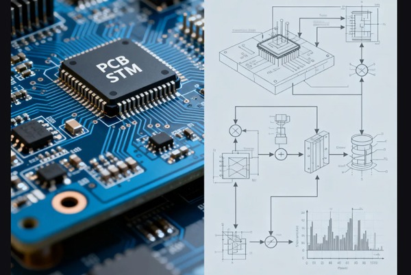
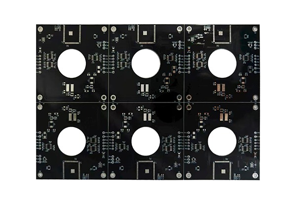
Печатные платы (ПХД) состоят из нескольких слоев проводящих и непроводящих материалов и служат в качестве монтажного основания для электронных компонентов. Стандартная плата содержит следующие ключевые компоненты:
- А. выравнивание размеровТокопроводящие пути сделаны из тонких медных проводов, которые отвечают за проведение тока между компонентами
- Прокладки и вибрации: медные контактные пункты для пайки компонентов с vias, соединяющими различные слои
- Паяльная маска (Soldermask)Изоляционное покрытие, защищающее медные провода от короткого замыкания
- Слой шелкового экрана: опознавательный слой для обозначения положения и ориентации элементов
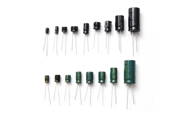
- Электронные компонентыВключая резисторы, конденсаторы, диоды, транзисторы и т.д.
Понимание этих базовых структур является первым шагом к успешному ремонту платы. Различные типы плат (однослойные, двухслойные или многослойные) требуют различных методов ремонта, а многослойные платы особенно сложны в ремонте.
Обычные типы неисправностей плат
Электрические платы могут выходить из строя по ряду причин, и признание проблемы является критически важным первым шагом в ремонте. Ниже приводятся пять наиболее распространенных типов неисправностей:
1. Нанесение телесных повреждений
Физические повреждения доски могут быть вызваны сбрасыванием, ударом или неправильной разборкой устройства. К их числу относятся:
- Сломанные или изогнутые платы
- Смещенные паяльные подушки
- Сломанные следы на теле
- Отдельные или отдельные компоненты
Неисправность элемента оборудования
Электронные компоненты могут выходить из строя из-за старения, перегрева или нестабильности напряжения:
- Конденсаторы, срабатывающие или протекающие
- Сожженные и обесцвеченные резисторы
- Разрыв интегральных схем (ICs)
- Транзистор или диодные шорты
3. Повреждение траектории проводника
Токопроводящие пути могут быть повреждены:
- Удары молнией или скачки напряжения
- Загрязнение металлической пылью
- Длительное перегрев
- Нормальная степень износа
4. Неисправная конструкция
Плохо спроектированные доски часто характеризуются:
- Неправильный интервал между компонентами
- Неадекватная маршрутизация
- Недостаточная тепловая конструкция
- Повторение одной и той же ошибки.
5. Сбои в электроснабжении
Проблема питания может привести к:
- Сгорание компонентов
- Короткое замыкание
- Включение защитной цепи
- Общая функциональная неисправность
Инструменты и оборудование для ремонта ПХД
Профессиональный ремонт требует нужных инструментов. Ниже приведен список основных и усовершенствованных инструментов ремонта:
Основные инструменты
- Паяльник с паяльным утюгомРекомендуется использовать регулируемую модель регулирования температуры (30-60W).
- 2. Паяльная проволокаДиаметр: 0,5-1мм
- ** дезактивационные инструменты **: оловянный сосос или линия отсоса
- - мультиметр.Для измерения напряжения, сопротивления и непрерывности
- - пинцет?: точные точечные пинцет для обработки небольших компонентов
- Увеличитель или микроскоп: : проверка мелких компонентов и соединений
- Комплект комплект отверток: : разборка коробок с оборудованием
Дополнительные инструменты
- Переделанная станция с горячим воздухомПрофессиональный демонтаж элементов, смонтированных на поверхности (SMD)
- - осциллографАнализ сигналов волн
- Антистатическая рабочая станция ESDПредотвращение повреждения чувствительных компонентов статическим электричеством
- Ручка для ремонта маски уф: : ремонт поврежденного слоя паяльной маски
- Станция перезагрузки BGA: ремонт чипа пакета массива шаровой сетки
Меры безопасности
Ремонт плат включает в себя электронные компоненты и потенциальные опасности, должны соблюдаться следующие правила безопасности:
- Отключение электроэнергииУбедитесь в Том, что оборудование полностью отключено и батареи сняты до обслуживания
- Статическая защита: надеть антистатический ремень на запястье и использовать антистатический мат
- Личная охрана:
- Очки для предотвращения брызг паяльника
- Работа в вентилируемом помещении или использование амортизатора дыма.
- Условия труда:
- Чистая, хорошо освещенная рабочая зона
- Держитесь подальше от легковоспламеняющихся материалов
- Безопасность инструмента:
- Правильно расставить горячие инструменты.
- Используйте правильный размер инструмента
Ремонт ПХД шаг за шагом
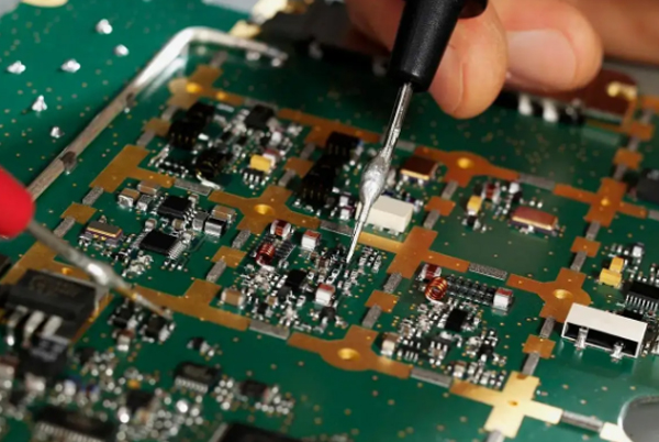
Первый шаг: визуальный осмотр
Тщательно проверьте электронную плату на наличие видимых повреждений:
- Сгоревшие или обесцвеченные участки
- Конденсаторы расширенные или утекающие
- Разрывы в ранах
- Свободные или отсутствующие компоненты
- Холодные суставы (скучные, безжизненные суставы)
Используйте увеличительное стекло или микроскоп для проверки на наличие незначительных повреждений.
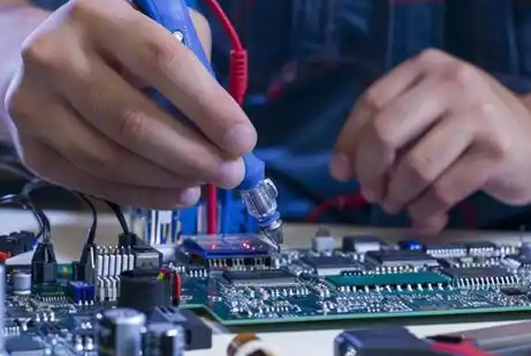
Этап 2: функциональное испытание
С помощью мультиметра можно выполнить следующие основные тесты:
- Проверьте правильное питание
- Испытательное напряжение в критических точках
- Измерение сопротивления подозрительных компонентов
- Проверить непрерывность регулировки с помощью сквозного испытания
В случае сложных неисправностей может потребоваться осциллограф для анализа сигнала.
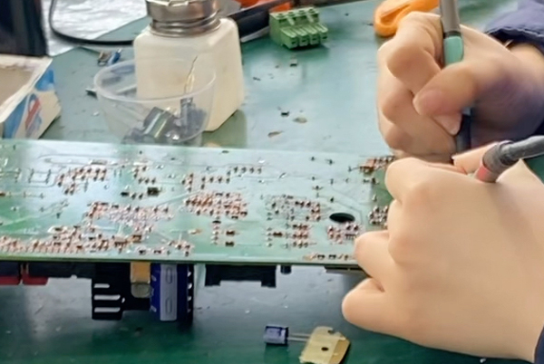
Шаг 3: удаление дефектного компонента
- Определить местоположение дефектного элемента
- Выберите метод опустошения в зависимости от типа компонента:
- Компоненты сквозных отверстий: используйте солончатор или паяльную проволоку
- SMD компоненты: используйте горячее воздушное оружие или переоборудование станции
- Тщательно удалите элемент, чтобы избежать повреждения колодок.
Шаг 4: ремонт прокладки и выравнивания
- Чистые подушки: используйте изопропиловый спирт и ватные тампоны
- Ремонт поврежденной арматуры:
- Содрать маску, чтобы открыть медные провода.
- Используйте тонкую медную проволоку или проводящую серебряную краску, чтобы соединить разбитые точки.
- Защитите зону ремонта с помощью ультрафиолетового солнцезащитного маска
- Ремонт полосканных колодок:
- Восстановление колодок с медной фольгой ленты
- Сверла и установка комплекта для ремонта блокнота
Шаг 5: установка новых компонентов
- Выберите элемент замены с соответствующими спецификациями
- Правильно разместить компонент:
- Обратите внимание на поляризованную ориентацию компонентов
- SMD компоненты размещаются точно с помощью пинцет
- Пресс-релиз:
- Пайка: сначала установите Один штифт для компонентов сквозных отверстий
- Компоненты SMD с использованием пасты паяльника и термофена
- Проверьте качество пайкового соединения:
- Должно быть гладким и блестящим
- Никакого сближения или ложного пайка
Этап 6: функциональная проверка
- Визуальный осмотр качества пайки
- Используйте мультиметр для проверки ключевых точек
- Поэтапное испытание на включение двигателя
- Испытание на полную функциональность
Специальные методы ремонта
Ремонт устройства крепления поверхности (SMD)
- Используйте пасту паяльника, чтобы точно наклеить пальто.
- Поместите компонент пинцет
- Тепло равномерно с тепловым пистолетом до тех пор, пока паяльник не затвердеет.
- Избегайте перегрева, что может вызвать "эффект надгробия" (Один конец составляющих искривлений).
Многослойный ремонт
- Используйте сквозной микроскоп для проверки внутреннего слоя.
- Для ремонта внутреннего слоя требуется специальное оборудование.
- Используйте медную проволоку или эпоксидную проводку для ремонта
Ремонт чипов BGA
- Используйте BGA rework station для точного регулирования температуры.
- Восстановить паяльный шар с помощью инструмента размещения мяча
- Рентгеновская проверка на качество пайки
Послеремонтные испытания и верификация
Полное тестирование является ключом к успешному ремонту:
- Базовое испытание:
- Испытание короткого замыкания питания
- Измерение статического тока
- Проверка напряжения в критических точках
- Функциональные испытания:
- Проверка входного и выходного сигналов
- Испытание на нагрузку
- Длительное время работы
- Экологические испытания (критическое оборудование)
- Циклическое изменение температуры
- Испытание на виброустойчивость
- Испытание на влажность
Рекомендации по превентивному техническому обслуживанию
Практические советы по продлению срока службы плат:
- Регулярно проводить чистку:
- Используйте сжатый воздух для удаления пыли
- Изопропиловый спирт для очистки контактных пунктов
- Контроль за состоянием окружающей среды:
- Избегайте высоких температур и высокой влажности окружающей среды
- Предотвращение загрязнения металлической пылью
- Защита от электрических помех:
- Использование регулируемого источника питания
- Установка волноуспокоителей
- Физическая защита:
- Избегать механического напряжения
- Используйте соответствующую фиксацию и амортизацию
Часто задаваемые вопросы
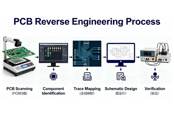
В: могу ли я восстановить плату без схемы?
О: да, но это сложно. Анализ направления цепи и метод сравнения можно вывести функцию, сложные схемы рекомендуется найти схематическую диаграмму.
В: как определить, поврежден ли конденсатор?
О: Визуальный осмотр на наличие выпуклостей или утечек, мультиметр для измерения значения емкости, ESR-метр для измерения эквивалентного последовательного сопротивления.
В: Повлияет ли ремонт на срок службы платы?
О: Профессиональный ремонт мало влияет на срок службы, но повторный ремонт, особенно при высоких температурах, сокращает срок службы компонентов.
В: какие платы не стоит ремонтировать?
A: Большие выгоревшие участки, поврежденные внутренние слои многослойных плат, дешевые платы или платы, снятые с производства и не имеющие доступа к компонентам.
В: как я могу узнать более продвинутые методы ремонта?
О: начать с простого ремонта, чтобы получить опыт, пройти профессиональную подготовку и изучить отраслевые стандарты, такие как IPC-7711/7721.
Похожие посты