PCB Montajı ve IPC Standartları
Elektronik üretimi alanında IPC standartları, tasarımdan üretime kadar her aşama için bilimsel spesifikasyonlar sağlayarak, ürünlerin performansı ve güvenilirliği üzerinde belirleyici bir rol oynamaktadır. baskılı devre kartı (PCB) montaj son ürünleri.
İçindekiler
IPC standartları nelerdir?
IPC standartları (eski adıyla Printed Circuit Association standartları, yeni adıyla Electronic Industries Association standartları) elektronik üretim endüstrisinde PCB tasarımından hammadde seçimine, montaj süreçlerinden son denetime kadar tüm süreci kapsayan bir kalite ölçüt sistemi olarak kabul edilmektedir. Küresel endüstri uzmanları tarafından ortaklaşa geliştirilen bu standart sistem, onlarca yıllık bir geliştirme ve iyileştirme sürecinden geçmiş ve elektronik ürünlerin güvenilirliğini ve tutarlılığını sağlamak için vazgeçilmez bir araç haline gelmiştir.
IPC Standartlarının Rolü
- Tasarım mühendislerine, aşağıdakileri sağlamak için bilimsel tasarım özellikleri sağlarlar PCB düzenleri elektrik performansı gereksinimlerini karşılar ve kolayca üretilebilir.
- Üreticilere proses parametreleri ve kalite kabulü için objektif kriterler sağlarlar.
- Tedarik zincirindeki tüm bağlantılar için tek tip bir “teknik dil” oluşturarak iletişim verimliliğini büyük ölçüde artırırlar.
IPC standartlarının kendileri yasal olarak bağlayıcı olmamakla birlikte, belirli IPC standart seviyelerine uyum, havacılık, tıbbi cihazlar ve otomotiv elektroniği gibi yüksek güvenilirliğe sahip elektronik ürün sektörlerindeki sözleşmelerde genellikle zorunlu bir gereklilik haline gelir.
Elektronik cihazlar minyatürleşme ve daha yüksek yoğunluk yönünde gelişmeye devam ettikçe ve kurşunsuz lehimleme gibi yeni süreçler daha yaygın hale geldikçe, IPC standartları da sürekli olarak güncellenmektedir.
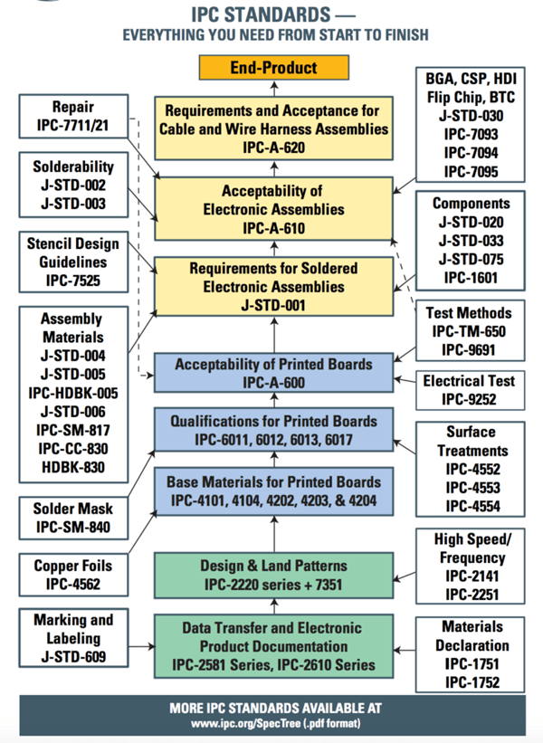
PCB montajı için temel IPC standartları
IPC-A-610
Elektronik montaj alanında en yaygın tanınan IPC standardı olan IPC-A-610, elektronik montajların kalite kabulü için ayrıntılı görsel kriterler sağlar. En son sürüm olan IPC-A-610J (2024'te piyasaya sürüldü), lehim bağlantı kalitesi ve bileşen yerleştirmeden mekanik montaja kadar çeşitli yönler için kabul kriterlerini tanımlar. En dikkat çekici özelliği, elektronik montajların farklı ürün uygulama senaryolarına dayalı olarak üç güvenilirlik seviyesine sınıflandırılmasıdır:
- Sınıf 1 – Genel Tüketici Elektroniği
- Oyuncaklar ve yaygın ev aletleri gibi düşük kullanım ömrü gereksinimleri ve zararsız kullanım ortamları olan günlük elektronik ürünlere uygulanabilir. Tutarsız lehim bağlantı parlaklığı veya hafif bileşen yanlış hizalaması gibi işlevselliği etkilemeyen küçük kozmetik kusurlara izin verilir.
- Sınıf 2 – Özel Servis Elektroniği
- İletişim cihazları ve endüstriyel kontrol sistemleri gibi daha uzun hizmet ömrü ve daha yüksek güvenilirlik gerektiren endüstriyel ve ticari ekipmanlara uygulanabilir. Sınıf 1'den daha sıkı proses kontrolü gereklidir ve kusurlara karşı tolerans önemli ölçüde azalır.
- Sınıf 3 – Yüksek Performanslı Elektronik
- Tıbbi yaşam destek sistemleri, havacılık elektroniği ve otomotiv güvenlik sistemleri gibi arıza olmadan sürekli çalışması gereken kritik ekipmanlara uygulanabilir. En katı kabul kriterleri uygulanır ve süreç kusurlarına neredeyse hiç tolerans gösterilmez.
Pratik uygulamalarda, IPC-A-610 çeşitli proses hatalarının özelliklerini ve kabul edilebilir sınırlarını belirtirken, IPC-J-STD-001 kaynak prosesi standartları çeşitli kaynak hatalarının türlerini ve kabul kriterlerini tanımlar.IPC-A-610 standardı, uygulamadan son denetime kadar tüm süreç boyunca kapsamlı kalite kontrolü sağlamak için tipik olarak IPC-J-STD-001 kaynak işlemi standartları ile birlikte kullanılır.
IPC-2221
IPC-2221 standardı, PCB tasarımı alanında köşe taşı niteliğinde bir belgedir.Baskılı devre kartı tasarımı için temel ilkeleri ve spesifikasyonları belirleyerek tasarım aşamasında üretilebilirlik, güvenilirlik ve performans optimizasyonu sağlar.
Bu standardın temel içeriği şunları içerir:
- Elektriksel Tasarım Özellikleri
- Sinyal bütünlüğünü sağlamak için farklı uygulama senaryoları için hat genişliği/aralığı gereksinimleri, empedans kontrol yöntemleri ve akım taşıma kapasitesi hesaplamaları.
- Mekanik Yapı Gereksinimleri
- Üretim hataları nedeniyle güvenilir olmayan iç katman bağlantılarını önlemek için delik halkası tasarımı, katmanlar arası hizalama toleransları ve kart kenarı işlemi gibi mekanik unsurları kapsar.
- Termal Yönetim Kılavuzları
- Yüksek güç yoğunluklu PCB'ler için ısı yayma deliği düzeni, termal direnç hesaplamaları ve yerel ısı yayma iyileştirmesi için tasarım önerileri sağlar.
- Malzeme Seçim İlkeleri
- Farklı elektrik performansı, çevresel uyumluluk ve maliyet gereksinimlerine dayalı olarak uygun alt tabaka malzemeleri, bakır folyo türleri ve yüzey işleme süreçlerinin seçiminde tasarımcılara rehberlik eder.
IPC-2221'in öne çıkan bir özelliği, genel bir standart olarak hizmet veren ve belirli PCB türleri (IPC-2222 sert kartlar, IPC-2223 esnek kartlar vb.) için bir dizi alt standartla birlikte eksiksiz bir tasarım standardı sistemi oluşturan modüler yapısıdır.
IPC-J-STD-001
IPC-J-STD-001, elektronik üretim endüstrisindeki en yetkili lehimleme süreci standardıdır. J-STD-001 lehimleme malzemeleri, proses parametreleri ve kalite kontrol için kapsamlı gereklilikler belirler.
Temel teknik içerik şunları içerir:
- Malzeme Özellikleri
- Lehim alaşımlarının bileşimini (örn. SAC305), flux tiplerini ve lehim pastası performans gereksinimlerini belirleyin, güvenilir lehimleme sağlamak için bileşim toleranslarını ve kirlilik sınırlarını tanımlayın.
- Süreç Gereksinimleri
- Manuel lehimleme, dalga lehimleme, yeniden akış lehimleme vb. için parametre yönergeleri sağlayın. Örneğin, yeniden akış lehimlemede, soğuk lehimlemeyi veya termal hasarı önlemek için sıcaklık bölgelerini ve likidus çizgisinin (TAL) üzerindeki süreyi kontrol edin.
- Kabul Kriterleri
- Lehim ıslanabilirlik açısı ve bağlantı morfolojisi gibi temel göstergelere dayalı olarak ürünleri sınıflandırın ve kabul edin, ürün sınıfına göre kategorize edin (Seviye 1/2/3).
- Eğitim ve Sertifikasyon Sistemi
- Süreç tutarlılığını artırmak için teorik ve pratik değerlendirmeler yoluyla standartların doğru uygulanmasını sağlayarak katı CIS (operatör) ve CIT (eğitmen) sertifikasyon prosedürlerini uygulayın.
Gerçek üretimde, J-STD-001 standardına uygun kaynak işlemi kontrolü hata oranını önemli ölçüde azaltabilir. Bu standarda sıkı sıkıya bağlı kalınması, kaynak kusur oranını ortalama 'tan fazla azaltabilir.
IPC-7351
ile yüzey montaj teknolojisi (SMT) ana akım süreç haline geliyor PCB montajıIPC-7351 standardının önemi giderek daha belirgin hale gelmiştir. Bu standart, SMT bileşenleri için ped tasarımını özel olarak ele alır ve bileşenlerin iyi bir bağlantı oluşumuyla güvenilir bir şekilde lehimlenebilmesini sağlamak için bilimsel hesaplama yöntemleri ve yerleşim özellikleri sağlar.
IPC-7351 standardının temel teknik özellikleri şunlardır:
Ped Boyutu Hesaplama Sistemi
- Bileşen paketi boyutlarına ve üretim toleranslarına dayanarak, farklı yoğunluk seviyelerinde ped boyutlarını hesaplamak için formüller sağlar. Standart üç yoğunluk seviyesi tanımlar:
- Seviye A (Düşük Yoğunluk): Daha geniş proses pencerelerine sahip daha büyük ped boyutları, yüksek güvenilirlikli uygulamalar için uygundur
- Seviye B (Orta Yoğunluk): Dengeli boyut ve yoğunluk, çoğu ticari ürün için uygundur
- Seviye C (Yüksek Yoğunluk): Kısıtlı alan tasarımları için minimum ped boyutları
Standart Ayak İzi Kitaplığı
- 0402 dirençlerden yüzlerce pimli BGA'lara kadar neredeyse tüm yaygın SMT paket tiplerini kapsar. Standart, her paket tipi için ayrıntılı boyut etiketlemesi ve önerilen ped desenleri sağlayarak tasarım çalışmalarını büyük ölçüde basitleştirir.
Üç Boyutlu Lehim Bağlantı Gereksinimleri
- Yalnızca iki boyutlu düzlemsel boyutlara odaklanmakla kalmaz, aynı zamanda topuk, ayak parmağı ve yan dolgu gereksinimleri dahil olmak üzere ideal üç boyutlu lehim bağlantı morfolojisini de belirtir. Bu, yüksek mekanik mukavemete ve iyi termal yorulma direncine sahip güvenilir lehim bağlantılarının oluşturulmasına yardımcı olur.
IPC-7351 standardına uygun ped tasarımlarının kullanılması, SMT montajının ilk geçiş verimini 'dan fazla artırabilir ve özellikle tombstoning ve köprüleme gibi tipik kusurları azaltarak tasarım verimliliğini ve doğruluğunu büyük ölçüde artırabilir.
PCB Montaj Sürecinde IPC Standartlarının Uygulanması
Tasarım Aşamasında IPC Standartlarının Uygulanması
IPC standartlarını ön uç PCB tasarımına dahil etmek, nihai montaj kalitesini sağlamak için en uygun maliyetli yöntemdir. Deneyimler, tasarım aşamasında sorunları belirleme ve düzeltme maliyetinin üretim sırasındaki maliyetin yalnızca 1/10'u olduğunu göstermektedir. IPC-2221 ve IPC-7351'e dayalı tasarım spesifikasyonlarının uygulanması aşağıdaki kilit noktalara odaklanmalıdır:
Tasarım Kuralı Yapılandırması: EDA araçlarında IPC uyumlu tasarım kural setleri oluşturun:
- Elektrik kuralları:İz genişliği/açıklığı, empedans kontrolü, akım taşıma kapasitesi
- Fiziksel kurallar:Ped boyutları, bileşen aralıkları, kart kenarı dışta tutma alanları
- Üretim kuralları:Minimum delik boyutları, dairesel halka genişlikleri ve lehim maskesi köprü boyutları
Örneğin, 1,6 mm kalınlığındaki FR-4 laminatlar için IPC-2221, kaplama zorluklarından kaçınmak için delik çapının kart kalınlığına oranının 1:3'ü geçmemesini önermektedir.Yüksek hızlı tasarımlarda, diferansiyel çift yönlendirmesi, empedans tutarlılığını sağlamak için standart olarak önerilen aralık kontrol yöntemlerini takip etmelidir.
Bileşen Kitaplığı Yönetimi: IPC-7351 uyumlu bir bileşen ayak izi kütüphanesi oluşturun ve sıkı bir yeni bileşen tanıtım süreci uygulayın:
- Tedarikçi bileşen boyut çizimlerinin doğruluğunu teyit edin
- Uygulama güvenilirliği gereksinimlerine göre Seviye A/B/C pedleri seçin
- Ped boyutlarını belirlemek için IPC tarafından sağlanan hesaplama formüllerini kullanın
- DFM (Üretilebilirlik için Tasarım) kontrollerinin yapılması
Termal Tasarım Hususları: Yüksek güçlü bileşenlerin özel muamelesi için IPC-2221 termal yönetim yönergelerini izleyin:
- Yeterli termal tahliye yolları sağlayın
- Yüksek ısılı bileşenleri kart kenarlarından ve hassas cihazlardan uzak tutun
- CTE (Termal Genleşme Katsayısı) eşleştirme sorunlarını göz önünde bulundurun
Tasarım İncelemeleri: Kritik dönüm noktalarında departmanlar arası tasarım incelemeleri gerçekleştirin, kontrol edin:
- Bileşen yerleşiminin SMT süreci gereksinimlerini karşılayıp karşılamadığı
- Test noktalarının otomatik test ekipmanı gereksinimlerini karşılayıp karşılamadığı
- Özel proses gereksinimlerinin (seçici lehimleme gibi) belirtilip belirtilmediği
Üretim ve Montaj Süreç Kontrolü
PCB montajı, tasarımların fiziksel ürünlere dönüştürüldüğü ve IPC standartlarının en yoğun şekilde uygulandığı kritik aşamadır. IPC-J-STD-001'e dayalı süreç kontrol sistemi şunları içermelidir:
Malzeme Kontrolü:
- Lehim pastası: J-STD-005 standardına uygun, viskozite, metal içeriği ve partikül boyutu dağılımını düzenli olarak test eden
- Flux: Lehimleme yöntemine (dalga/reflow) göre uygun tipleri seçin
- Bileşenler: Özellikle neme duyarlı cihazlar (MSD) için saklama koşulları ve raf ömrü yönetimi
Süreç Parametre Optimizasyonu:
- Lehim pastası baskısı: Şablon kalınlığının ve açıklık boyutlarının IPC-7525'e göre doğrulanması
- Yerleştirme:IPC-9850 ekipman performans standartlarına uygunluğu sağlamak için doğruluk kalibrasyonu
- Reflow lehimleme:Hem lehim üreticisi hem de IPC standart gereksinimlerini karşılamak için sıcaklık profili doğrulaması
Süreç İzleme:
- İlk ürün denetimi: IPC-A-610 kullanılarak tam boyutsal denetim
- Süreç örneklemesi:Lehim pastası kalınlığı ve yeniden akış sonrası bağlantı kalitesi gibi temel parametrelerin istatistiksel süreç kontrolü (SPC)
- Ekipman bakımı:Süreç istikrarını korumak için düzenli kalibrasyon ve bakım
Kalite Denetimi ve Kusur Analizi
IPC-A-610'a dayalı kalite denetim sistemi, son ürünlerin gereksinimleri karşılamasını sağlamak için son savunmadır.Etkili bir denetim planı şunları dikkate almalıdır:
Muayene Yöntemi Seçimi:
- Görsel inceleme: Standart resimlerle karşılaştırmak için uygun büyütme ve ışıklandırma kullanılması
- AOI (Otomatik Optik Muayene):IPC standartlarına dayalı programlama kabul eşikleri
- X-ray kontrolü:BGA ve QFN gibi gizli bağlantılar için
- İşlevsel test:Elektrik performansının tasarım gereksinimlerini karşıladığının doğrulanması
Kusur Sınıflandırması ve Ele Alınması:
- Kritik kusurlar: İşlevselliği veya güvenliği doğrudan etkiler, 0 elenmelidir
- Küçük kusurlar:AQL (Kabul Edilebilir Kalite Seviyesi) örneklemesi ile değerlendirilen, işlevi etkilemeyen kozmetik sorunlar
- Süreç uyarıları:Sınırları aşmıyor ancak spesifikasyon sınırlarına yaklaşıyor, süreç ayarlamalarını tetikliyor
Kök Neden Analizi:
Yinelenen kusurlar için, sorunların tasarımdan mı, malzemelerden mi yoksa süreçlerden mi kaynaklandığını belirlemek üzere balık kılçığı diyagramlarını, 5Neden'i ve derinlemesine analiz için diğer araçları kullanın, ardından düzeltici önlemler alın. IPC standartları bu süreçte objektif kriterler sağlayarak sübjektif tartışmaları önler.
Güvenilirlik Doğrulaması ve Sürekli İyileştirme
Yüksek güvenilirlikli ürünler için rutin denetimler tek başına yeterli değildir; IPC tabanlı güvenilirlik doğrulaması da gereklidir:
Çevresel Stres Testi:
- Sıcaklık döngüsü: IPC-9701 tarafından yönlendirilen termal yorulma testi
- Titreşim testi:Ürün uygulama ortamına göre uygun koşulları seçin
- Nemli ısı yaşlandırması:Zorlu koşullar altında uzun vadeli güvenilirliğin değerlendirilmesi
Arıza Analizi:
Başarısız test numunelerinin derinlemesine analizi:
- Kesit alma: Lehim bağlantı mikroyapısının gözlemlenmesi
- SEM/EDS:Arıza yüzey morfolojisi ve bileşiminin analizi
- Akustik mikroskopi:Delaminasyon ve boşlukları tespit etme
Sürekli İyileştirme:
Standartlaştırılmış bir iyileştirme süreci oluşturun:
- Üretim verilerini ve müşteri geri bildirimlerini toplayın
- İyileştirme fırsatlarını belirleyin
- İyileştirme planları geliştirin
- Etkinliği doğrulayın
- İlgili belgelerin standartlaştırılması ve güncellenmesi
Bu sistematik IPC standart uygulama yaklaşımı sayesinde, PCB montaj şirketleri tasarımdan teslimata kadar kapsamlı bir kalite kontrol sistemi kurabilir ve sürekli olarak yüksek kaliteli ürünler ve hizmetler sağlayabilir.

Topfast’ın Profesyonel Standartları Uygulama Yetenekleri
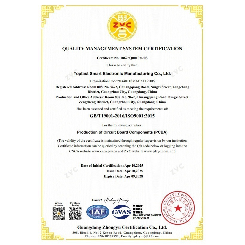
ISO 9001 ve IATF 16949 sertifikalı bir profesyonel olarak PCB üreticisiTopfast, IPC standartlarını her seviyede uygulamak için kapsamlı yeteneklere sahiptir:
Ekipman ve Süreç Kapasiteleri:
- Yüksek hassasiyetli SMT hatları (01005 bileşen yerleştirme özelliği)
- Karışık montaj gereksinimleri için seçici lehimleme sistemleri
- 3D SPI ve AOI tam denetim sistemleri
- Gizli BGA/QFN bağlantıları için X-ray kontrolü
Kalite Kontrol Sistemi:
- Müşteri ürün türlerine göre özelleştirilmiş denetim planları
- Kapsamlı Malzeme İnceleme Kurulu (MRB) süreci
- Gelişmiş laboratuvar test ekipmanları (metalografik kesit analizi dahil)
- Eksiksiz veri izlenebilirlik sistemi
Başarı Hikayeleri:
- Tıbbi izleme cihazları: IPC Sınıf 3 standartlarına ulaşıldı, 3 yıl boyunca %0,1 arıza oranı
- Endüstriyel kontrolörler:Karma seviyeli uygulama, güvenilirlik gereksinimlerini karşılarken maliyet tasarrufu sağladı
- Otomotiv ECU'ları:Müşteri denetimlerini sıfır hatayla geçerek Tier 1 tedarikçisi oldu
Bilimsel IPC standart seviyesi seçimi ve profesyonel uygulama yetenekleri sayesinde Topfast, müşterilerin kalite ve maliyet arasında en uygun dengeyi elde etmelerine yardımcı olarak ürün pazarında başarı için sağlam bir temel oluşturur.


İlgili Yazılar