Lehim Pastası Kontrolü
İçindekiler
Lehim Pastası Muayenesi Nedir?
Lehim Pastası Denetimi (SPI), SMT proseslerinde lehim pastası baskısının kalitesini ve hassasiyetini değerlendirmek için özel olarak tasarlanmış, optik prensiplere dayalı otomatik bir denetim teknolojisidir.SMT montaj üretim hatlarında lehim pastası, çelik bir şablon aracılığıyla PCB pedlerine hassas bir şekilde basılır. Küçük sapmalar bile daha sonra kusurlara yol açabileceğinden, bu işlemin doğruluğu kritik öneme sahiptir.
Lehim Pastası Denetiminin Rolü
Modern SPI sistemleri tipik olarak yüksek çözünürlüklü kameralar, çok açılı aydınlatma ve gelişmiş görüntü işleme algoritmalarını entegre eder.Ne zaman PCB Sistem, denetim alanına girdiğinde lehim pastasının birden fazla açıdan yüksek çözünürlüklü görüntülerini yakalar ve ardından her bir lehim pastası noktasının hacmi, yüksekliği, alanı ve konumsal ofseti gibi temel parametreleri hassas bir şekilde ölçmek için 3D yeniden yapılandırma teknolojisini kullanır.Geleneksel iki boyutlu denetimin aksine, gelişmiş SPI sistemleri mikron seviyesine ulaşan algılama doğruluğu ile gerçek üç boyutlu ölçüm verileri sağlar ve manuel denetimin yeteneklerini çok aşar.
Lehim pastası denetimi, SMT üretim sürecinde birçok kritik rol oynar.İlk olarak, lehim pastası baskısının homojenliğini, uygunluğunu ve konumsal doğruluğunu kapsamlı bir şekilde yansıtan bir "yerleştirme kalitesi aynası" görevi görür. İkinci olarak, "lehimleme kusurlarının koruyucusu" olarak SPI, yetersiz, aşırı veya yanlış hizalanmış lehim pastası gibi potansiyel lehimleme sorunlarını erken bir aşamada tespit ederek kusurların sonraki süreçlere girmesini önleyebilir. Ek olarak, SPI sistemleri "verimliliğin hızlandırıcısı" olarak hareket eder, gerçek zamanlı kalite izleme ve anında geri bildirim yoluyla zayıf lehim pastasının neden olduğu yeniden işleme ve hurdayı önemli ölçüde azaltır, böylece genel üretim verimliliğini artırır.
Modern SPI sistemleri artık sadece basit denetim araçları değildir; her PCB için otomatik olarak ayrıntılı denetim raporları oluşturmalarını ve lehim pastası kalite verilerini kaydetmelerini sağlayan güçlü veri analizi ve işleme yetenekleriyle donatılmıştır. Bu geçmiş veriler proses optimizasyonu, kalite izlenebilirliği ve sürekli iyileştirme için çok değerlidir ve SPI sistemlerini üreticilerin daha rafine proses kontrolü elde etmelerine yardımcı olan "veri odaklı uzmanlar" haline getirir.
Lehim Pastası Denetiminin Önemi
Eksiksiz olarak yüzey montaj teknoloji̇si̇ (SMT) sürecinde, lehim pastası denetimi vazgeçilebilir bir adım değil, nihai ürünün kalitesini sağlayan kritik bir kontrol noktasıdır.Lehim pastası, elektronik bileşenler ve PCB'ler arasında elektriksel ve mekanik arayüz görevi görür ve kalitesi milyonlarca lehim bağlantısının güvenilirliğini doğrudan etkiler.Lehim pastasındaki küçük bir kusur bile tüm elektronik cihazın arızalanmasına neden olabilir ve otomotiv elektroniği ve tıbbi cihazlar gibi kritik alanlarda bu tür arızalar ciddi sonuçlara yol açabilir.
1.Lehim Pastası Kalınlığı
Lehim pastası kalınlığı, SPI denetimindeki temel parametrelerden biridir ve lehim bağlantısının stabilitesini doğrudan etkiler.Çok ince lehim pastası, yetersiz bağlantı mukavemetine neden olarak soğuk lehim bağlantılarına veya eksik lehimlemeye yol açabilir; tersine, aşırı kalın lehim pastası, özellikle BGA veya QFN gibi ince aralıklı bileşenler için köprüleme kısa devrelerine neden olabilir.SPI sistemleri, her bir lehim pastası noktasının yüksekliğini ve hacmini hassas bir şekilde ölçerek prosesin gerektirdiği optimum aralıkta olmalarını sağlar ve böylece bu yaygın lehimleme hatalarını önler.
2.Kalite Kontrol Perspektifinden
Lehim pastası denetimi, modern kalite yönetimi felsefesi olan "düzeltme yerine önleme "yi temsil eder.Geleneksel kaynak sonrası denetimin aksine SPI, sorunları kaynak öncesinde tespit ederek yeniden işleme maliyetlerini ve malzeme israfını önemli ölçüde azaltır.SPI sistem denetiminden sonra, SMT üretim hatları tipik olarak ilk geçiş veriminde -25'lik bir artış ve kalite maliyetlerinde 'un üzerinde bir azalma görür ve yatırım geri ödeme süresi genellikle bir yılı geçmez.
3. Süreç optimizasyonu için
SPI sistemleri tarafından sağlanan büyük miktarda veri çok değerlidir.Süreç mühendisleri, süreç yeterlilik endekslerini (CPK), kusur dağılım modellerini ve lehim pastası baskısındaki zaman eğilimlerini analiz ederek, üretim süreçlerini sürekli olarak optimize etmek için şablon tasarımını, silecek parametrelerini ve baskı ayarlarını hassas bir şekilde ayarlayabilirler.Örneğin, SPI verileri belirli konumlarda sistematik bir düşük hacimli lehim pastası gösteriyorsa, şablon açıklıklarının tıkalı olup olmadığını veya silecek basıncının eşit olup olmadığını kontrol etmek gerekebilir.
Havacılık, otomotiv elektroniği ve tıbbi cihazlar gibi yüksek güvenilirliğe sahip elektronik üretim sektörlerinde lehim pastası kontrolü vazgeçilmez bir proses adımı haline gelmiştir.Bu sektörlerdeki ürünler genellikle aşırı çevre koşullarına dayanmak zorundadır ve herhangi bir lehimleme hatası feci sonuçlara yol açabilir. Üreticiler katı lehim pastası kontrol standartları uygulayarak ürün güvenilirliğini önemli ölçüde artırabilir, sahadaki arıza oranlarını azaltabilir ve marka itibarını koruyabilir.
Lehim Pastası Muayene Standartları
Lehim pastası denetiminde tutarlılık ve güvenilirlik sağlamak için sektör, bileşen analizinden mekanik performans testine kadar birçok boyutu kapsayan kapsamlı bir denetim standartları seti oluşturmuştur.Bu standartlar sadece SPI ekipmanının parametre ayarlarına rehberlik etmekle kalmaz, aynı zamanda lehim pastası baskı işlemlerini değerlendirmek için objektif bir temel sağlar.
1.Akı Kalıntısı Korozyon Testi
JS.Z-3197 ve IPC-TM-650 gibi standartlara göre, metal yüzeylerdeki flaks kalıntılarının potansiyel korozyon riskini değerlendirmek için hızlandırılmış yaşlandırma testleri yapılır.Testler tipik olarak numunelerin yüksek sıcaklıklı, yüksek nemli ortamlara maruz bırakılmasını ve ardından korozyon belirtilerini incelemek için mikroskobik ve kimyasal analizleri içerir.Bu test özellikle temiz olmayan lehim pastaları için kritik önem taşır, çünkü kalıntı aktif maddeler ürünün kullanım ömrü boyunca kademeli olarak korozyona neden olabilir.
2.İzolasyon Direnç Testi
Test, gerçek çalışma koşullarını simüle eder ve güvenlik standartlarına uygunluğu sağlamak için bitişik iletkenler arasındaki direnç değerini ölçer.Bu özellikle yüksek yoğunluklu PCB'ler için önemlidir, çünkü küçük kaçak akımlar bile devre arızalarına neden olabilir.Test koşulları tipik olarak, en ağır koşullar altında performansı değerlendirmek için 85°C sıcaklık ve bağıl nemde çift stresi içerir.
3.Elektromigrasyon ve Kaçak Akım Testi
İyon kirliliği ve nem mevcut olduğunda, metal iyonları bir elektrik alanının etkisi altında göç ederek yalıtımın bozulmasına ve hatta kısa devrelere yol açabilir.Test, bir ön gerilim uygular ve lehim pastası formülasyonunun elektron göçüne karşı direncini değerlendirmek için akım değişikliklerini izler.Standartlara uygun lehim pastası, ürünün beklenen kullanım ömrü boyunca istikrarlı elektrik özelliklerini korumalıdır.
4.Lehim Eklemi Güvenilirlik Testi
Hassas kuvvet ölçüm ekipmanı, kırılma meydana gelene kadar lehim bağlantısına kademeli olarak artan kuvvet uygulamak ve maksimum kuvvet yük taşıma kapasitesini kaydetmek için kullanılır.Bu test sadece lehim pastasının performansını değerlendirmekle kalmaz, aynı zamanda tüm lehimleme sürecinin güvenilirliğini de doğrular. Titreşim stresine maruz kalan otomotiv elektroniği gibi uygulamalar için lehim bağlantısının mekanik mukavemeti kritik bir güvenilirlik göstergesidir.
5.X-ışını ve Kesit Analizi
X-ray görüntüleme kabarcıklar, boşluklar ve yetersiz dolgu gibi iç kusurları tahribatsız bir şekilde tespit edebilir; kesit analizi ise mikroskobik gözlem yoluyla arayüz yapısı ve metaller arası bileşik oluşumu hakkında daha ayrıntılı bilgi sağlar.Özellikle BGA'lar ve CSP'ler gibi gizli lehim bağlantıları için bu teknikler kalite değerlendirmesinin tek etkili yoludur.
6. Çevresel Stres Testi
Bunlar, çeşitli stres koşulları altında lehim bağlantılarının performans kararlılığını kapsamlı bir şekilde değerlendiren titreşim, şok, termal döngü ve düşme testlerini içerir.Örneğin, termal döngü testleri, gündüz-gece sıcaklık farklarının veya cihaz güç döngülerinin neden olduğu sıcaklık dalgalanmalarını simüle ederek lehim bağlantılarının yorulma direncini doğrular. Bu hızlandırılmış yaşlandırma testleri, gerçek kullanım ortamlarında lehim bağlantılarının uzun vadeli güvenilirlik performansını tahmin edebilir.
Lehim Pastası Kontrol Süreci
Lehim pastası denetiminin uygulanması, denetim sonuçlarının doğruluğunu ve tutarlılığını sağlamak için titiz, sistematik bir süreç izler.Ekipman hazırlığından veri analizine kadar her adımın kendine özgü teknik gereksinimleri ve çalışma standartları vardır.
1.Denetim Öncesi Sistem Hazırlığı
SPI'ın etkin çalışmasını sağlamanın temeli.Bu, ölçüm doğruluğunu doğrulamak için standart bloklar kullanarak ekipmanın düzenli kalibrasyonunu; farklı lehim pastası alaşımları ve PCB yüzey işlemleri farklı aydınlatma şemaları gerektirdiğinden uygun aydınlatma kaynaklarının seçimini ve belirli ürün özelliklerine göre uygun parametre eşiklerini ve denetim alanlarını ayarlayarak denetim programının optimizasyonunu içerir.Modern SPI sistemleri genellikle otomatik kalibrasyon işlevleri sunar, ancak operatörler yine de sistem performansını düzenli olarak doğrulamalıdır.
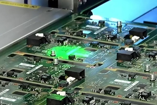
2.Denetim Sırasında Gerçek Zamanlı İzleme
SPI'ın temel değeri.PCB denetim alanına girdiğinde, sistem saniyeler içinde tam pano taramasını tamamlar ve her lehim pastası noktası için üç boyutlu morfoloji verileri oluşturur.Gelişmiş algoritmalar bu ölçüm değerlerini önceden tanımlanmış standartlarla karşılaştırarak yetersiz hacim, şekil bozuklukları veya konumsal kaymalar gibi anormallikleri tespit eder.Kullanıcı arayüzü, hızlı değerlendirme için renk kodlu görseller kullanarak tipik olarak kusur konumlarını ve önem düzeylerini görüntüler.
3.Veri Kaydı ve Analizi
SPI sisteminin akıllı temeli.Ölçüm değerleri, kusur görüntüleri ve istatistiksel dağılımlar dahil olmak üzere her PCB için eksiksiz denetim verileri otomatik olarak saklanır.Bu geçmiş veriler proses yeterlilik analizi, trend grafikleri ve Pareto hata analizi oluşturmak için kullanılabilir ve sistemik sorunların ve proses dalgalanmalarının belirlenmesine yardımcı olur.Bazı gelişmiş sistemler, insan gözünün tespit etmesi zor olan büyük veri kümelerindeki ince desenleri ortaya çıkarmak için makine öğrenimi teknolojisini de kullanabilir.
4.Kapalı Döngü Geri Besleme Kontrolü
SPI'ı sadece bir denetim aracı olmaktan çıkarıp bir süreç optimizasyon motoruna dönüştürür.Sistemik kusurlar tespit edildiğinde, SPI sistemi baskı makinesine silecek basıncının veya baskı hızının değiştirilmesi gibi ayar talimatlarını otomatik olarak gönderebilir.Bu gerçek zamanlı geri bildirim mekanizması, insan müdahalesinin neden olduğu gecikmeleri ve hataları önemli ölçüde azaltarak gerçek akıllı süreç kontrolü sağlıyor.Yüksek karışımlı üretim ortamlarında, sistem ayrıca farklı ürünler için parametre ayarlarını otomatik olarak alabilir ve değişim süresini kısaltır.
5.Denetim Sonuçlarının Görselleştirilmesi
Kalite iletişimi için önemli bir araç.SPI sistemi tarafından üretilen raporlar tipik olarak kusur konum haritalarını, temel parametre istatistiklerini ve süreç yeterlilik endekslerini içerir.Bu raporlar, gerekli düzeltici eylemleri tetiklemek için ilgili paydaşlara otomatik olarak gönderilebilir. Müşteri denetimleri veya sertifikasyon gereksinimleri için sistem, izlenebilirlik gereksinimlerini karşılamak üzere endüstri standardı formatlarda denetim kayıtları da oluşturabilir.
6. Sürekli İyileştirme Döngüsü
SPI değerini en üst düzeye çıkarma.Proses ekipleri, denetim verilerini düzenli olarak gözden geçirerek uzun vadeli eğilimleri belirleyebilir, iyileştirme önlemlerinin etkinliğini değerlendirebilir ve gelecekteki optimizasyon yönlerini planlayabilir. Bu veri odaklı iyileştirme yaklaşımı, geleneksel deneme-yanılma yöntemlerinden daha sistematik ve etkilidir, istikrarlı kalite iyileştirmeleri ve kusur oranlarının azaltılmasını sağlar.
Lehim Pastası Denetiminde Sık Karşılaşılan Sorunlar
Gerçek üretim proseslerinde, lehim pastası kontrolü çeşitli teknik zorluklar ve operasyonel sorunlarla karşılaşabilir.Bu yaygın sorunları ve çözümlerini anlamak, SPI sistemlerinin faydalarını en üst düzeye çıkarmaya ve denetim sonuçlarının güvenilirliğini sağlamaya yardımcı olabilir.
Soru 1: SPI sistemi eşit olmayan lehim pastası kalınlığı tespit ediyor, ancak gerçek baskı kalitesi iyi.Bunun nedeni ne olabilir?
Çözüm: Bu durum tipik olarak ölçüm hatalarından kaynaklanır. İlk olarak, Z ekseni ölçüm doğruluğunun gereksinimleri karşıladığından emin olmak için SPI ekipmanının kalibrasyon durumunu kontrol edin. İkinci olarak, PCB desteğinin düz olup olmadığını değerlendirin; eğri levhalar yanlış yükseklik değişimlerine neden olabilir. Ayrıca, farklı metaller farklı yansıtma özelliklerine sahip olduğundan, lehim pastası alaşım bileşiminin program ayarlarıyla uyumlu olduğunu doğrulayın. Son olarak, aşırı güçlü veya zayıf aydınlatma 3D rekonstrüksiyonun doğruluğunu etkileyebileceğinden aydınlatma ayarlarının uygun olduğunu onaylayın.
Soru 2: SPI denetiminde yanlış pozitif oranı nasıl azaltılabilir?
Çözüm: Yanlış pozitifler tespit verimliliğini azaltır ve önlemlerin bir kombinasyonu ile iyileştirilebilir. Aşırı katı standartlardan kaçınmak için tespit eşiği ayarlarını optimize edin; farklı boyutlardaki pedler için farklı kabul kriterleri belirlemek üzere bölge sınıflandırma işlevini kullanın; karakter işaretleri gibi alakasız basılı özellikleri göz ardı etmek için akıllı filtreleme algoritmalarını etkinleştirin; sistemi gerçek kusurlar ile kabul edilebilir süreç varyasyonları arasında daha iyi ayrım yapacak şekilde eğitmek için tipik kusur örneklerinden oluşan bir kütüphane oluşturun. Süreç iyileştirmelerine uyum sağlamak için tespit programının düzenli olarak güncellenmesi de önemlidir.
Soru 3: Yüksek yansıtıcı PCB yüzeyleri SPI tespitini zorlaştırdığında ne yapılmalıdır?
Çözüm: Altın yüzeyler gibi yüksek oranda yansıtıcı PCB'ler için özel önlemler alınabilir. Doğrudan yansımayı azaltmak için ışık kaynağı açısını ayarlayın ve düşük açılı aydınlatma kullanın; ayna yansıması girişimini bastırmak için polarizasyon filtrelemesini etkinleştirin; farklı aydınlatma koşullarında görüntüleri birleştirmek için programda çoklu pozlama tekniklerini kullanın; yüzey optik özelliklerini iyileştirmek için yardımcı kaplamalar (geçici mat sprey gibi) kullanmayı düşünün. Bazı üst düzey SPI sistemleri, yüksek yansıtıcı yüzeylerin yarattığı zorlukların üstesinden gelmek için özel olarak tasarlanmış özel dalga boylu ışık kaynaklarıyla da donatılmıştır.
Soru 4: SPI ve AOI denetim sonuçları arasındaki uyuşmazlıklar nasıl ele alınmalıdır?
Çözüm: SPI geçtiğinde ancak AOI lehimleme kusurları tespit ettiğinde, tutarsızlığın nedenlerini sistematik olarak analiz edin. Algılamadan sonra lehim pastası çökebileceği veya oksitlenebileceği için zaman gecikmelerini kontrol edin; aşırı basınç lehim pastası ekstrüzyonuna neden olabileceğinden bileşen montaj basıncını değerlendirin; uygun olmayan sıcaklık dağılımı lehimleme sorunlarına neden olabileceğinden yeniden akış eğrisinin uygun olup olmadığını düşünün; standart koordinasyonunda boşluklar olabileceğinden iki algılama standardının uyumlu olup olmadığını doğrulayın. Bir SPI-AOI korelasyon analizi veritabanı oluşturmak, temel nedenin belirlenmesine yardımcı olabilir.
Soru 5: SPI verileri lehim pastası baskı süreçlerini optimize etmek için nasıl kullanılabilir?
Çözüm: SPI verileri süreç optimizasyonu için değerli bir kaynaktır.Şablon tasarımı veya yazıcı parametreleriyle ilgili kalıpları belirlemek için kusurların uzamsal dağılımını analiz edin; mevcut sürecin kararlılığını ölçmek için süreç yeterlilik endeksini (CPK) hesaplayın; malzeme, ekipman, yöntem ve çevresel faktörlerin etkilerini ayırt etmek için kök neden analizi yapın; optimum parametre kombinasyonunu bilimsel olarak belirlemek için DOE (deney tasarımı) uygulayın; anahtar parametre değişikliklerinin eğilimini gerçek zamanlı olarak izlemek için istatistiksel süreç kontrol (SPC) çizelgeleri oluşturun. Bu yöntemler sayesinde baskı kalitesinde veri odaklı sürekli iyileştirme sağlanabilir.
Lehim Pastası Muayenesi Uygulama Alanları
Lehim pastası kontrol teknolojisi, tüketici elektroniğinden yüksek güvenilirliğe sahip ekipmanlara kadar elektronik üretiminin tüm alanlarına nüfuz etmiştir. Farklı endüstriler, kalite gereksinimlerine ve ürün özelliklerine göre benzersiz SPI uygulama modelleri geliştirmiştir.
Tüketici Elektroniği Üretimi
Akıllı telefonlar, tabletler ve giyilebilir cihazlar gibi ürünler için SPI sistemleri öncelikle yüksek yoğunluklu ara bağlantı (HDI) panolarının denetlenmesindeki zorlukları ele alır. Bu ürünler tipik olarak 0,3 mm'ye kadar ince ped aralıklarıyla 01005 veya daha da küçük bileşenler kullanır ve lehim pastası baskısında son derece yüksek hassasiyet gerektirir. Tüketici elektroniği üreticileri genellikle yüksek hacimli üretim programlarına uyum sağlamak için yüksek hızlı SPI ekipmanı kullanırken, hızlı hat değişimleri ve süreç optimizasyonu için SPI verilerinden yararlanırlar.
Otomotiv Elektroniği Sektörü
Motor kontrol üniteleri, güvenlik sistemleri ve ADAS modülleri gibi kritik bileşenler, herhangi bir lehimleme hatası ciddi güvenlik riskleri oluşturabileceğinden sıfır hata kalitesine ulaşmalıdır. Otomotiv elektroniği üreticileri genellikle 0 SPI denetimi uygular ve izlenebilirlik gereksinimlerini karşılamak için uzun vadeli veri kayıtları tutar. Denetim standartları da daha katıdır, tipik olarak tüketici elektroniği için olanlardan -50 daha katıdır. Ek olarak, termal-mekanik yorulma analizi gibi özel güvenilirlik testleri gereklidir.
Medikal Elektronik Sektörü
İmplante edilebilir cihazlar, teşhis aletleri ve tıbbi görüntüleme sistemleri son derece yüksek uzun vadeli güvenilirlik gerektirir. Bu uygulamalar genellikle gümüş içeren malzemeler gibi özel lehim pastası alaşımları kullanır ve SPI programlarının bu alaşımların özelliklerini doğru bir şekilde ölçmek için buna göre ayarlanmasını gerektirir. Medikal üretim aynı zamanda süreç doğrulamasını da vurgular ve SPI sistemlerinin medikal düzenleme gerekliliklerine uygunluğu göstermek için kapsamlı doğrulama belgeleri sağlaması gerekir.
Havacılık ve Savunma Elektroniği Sektörü
Uydular, aviyonikler ve askeri ekipmanlar aşırı sıcaklık dalgalanmalarına, titreşimlere ve radyasyon ortamlarına dayanmalıdır. Bu uygulamalar için SPI denetimi yalnızca geleneksel parametrelere odaklanmakla kalmaz, aynı zamanda lehim pastası mikro yapı bütünlüğünün ve safsızlık içeriğinin özel olarak değerlendirilmesini gerektirir. Denetim verileri, eksiksiz bir kalite kanıt zinciri oluşturmak için malzeme sertifikasyonu ve proses kalifikasyonu ile yakından entegre edilmelidir.
Endüstriyel Elektronik ve Enerji Sistemleri
Güç kontrol ekipmanları, endüstriyel otomasyon ve yenilenebilir enerji sistemleri de dahil olmak üzere, bu uygulamalar karışık teknolojiler ve büyük boyutlu PCB'ler ile karakterize edilir.SPI sistemleri, küçük SMD bileşenlerinden yüksek güçlü modüllere kadar çok çeşitli lehim bağlantılarını işlemelidir ve algılama prosedürleri oldukça esnek ve uyarlanabilir olmalıdır.Bu cihazların tipik olarak uzun ömürlü olması gerektiğinden, lehim pastası algılama verileri uzun vadeli güvenilirlik tahmin modelleriyle birleştirilmelidir.
İletişim Altyapısı
5G baz istasyonları, ağ ekipmanları ve elektronik üretimi yüksek frekans performansı için özel gereksinimlere sahip olan veri merkezi donanımı gibi.Lehim pastasının geometrik şekli ve yüzey kalitesi yüksek frekanslı sinyal iletimini etkiler, bu nedenle SPI denetimi bu özel parametrelere odaklanmalıdır. Milimetre dalga uygulamaları, lehim pastasının mikroskobik yüzey pürüzlülüğünün denetlenmesini bile gerektirir ve bu da SPI sistemlerine daha yüksek çözünürlük gereksinimleri getirir.
Elektronik teknolojisinin ilerlemesiyle birlikte esnek elektronik, 3D paketleme ve paket içinde sistem (SiP) gibi yeni ortaya çıkan alanlar da lehim pastası denetimi için yeni fırsatlar ve zorluklar sunmaktadır.Bu geleneksel olmayan uygulamalar, SPI sistemlerinin düzlemsel olmayan alt tabakalar ve üç boyutlu ara bağlantılar gibi yeni yapıların denetim ihtiyaçlarını karşılamak için daha yüksek uyarlanabilirliğe ve yenilikçi denetim algoritmalarına sahip olmasını gerektirir.
Özet
Lehim pastası denetim teknolojisi, elektronik ürünlerin minyatürleştirilmesi, yüksek yoğunluk ve yüksek güvenilirlik gereksinimleri ile önemi giderek artan modern elektronik üretiminde vazgeçilmez bir kalite güvence önlemine dönüşmüştür.Teknik açıdan bakıldığında SPI sistemleri, yüksek hassasiyetli 3D ölçüm ve akıllı veri analizi yoluyla lehim pastası baskı kalitesi üzerinde kapsamlı kontrol sağlayarak kalite kontrolünü kaynak öncesi aşamaya taşır ve kusur maliyetlerini ve risklerini önemli ölçüde azaltır.
Endüstri 4.0 ve akıllı üretimin ilerlemesiyle, lehim pastası denetimi bağımsız bir denetim sürecinden entegre bir süreç kontrol düğümüne dönüşmektedir.Modern SPI sistemleri, MES (Üretim Yürütme Sistemleri) ile derin entegrasyon yoluyla denetim verilerinin kurumsal düzeydeki kalite sistemleriyle sorunsuz entegrasyonunu sağlar; yapay zeka ve makine öğrenimi teknolojilerinden yararlanarak SPI’nın kusur tanımlama yetenekleri ve kestirimci bakım işlevleri önemli ölçüde geliştirilmiştir; dijital ikiz teknolojisine dayalı sanal devreye alma ve süreç optimizasyonu, SPI verilerinin değerini daha da artırır.
Ürün yaşam döngülerinin giderek kısaldığı küresel rekabet ortamında, yalnızca en gelişmiş proses kontrol ve kalite yönetimi teknolojilerinde uzmanlaşan şirketler tutarlı bir şekilde yüksek güvenilirliğe sahip ürünler sunabilir, müşterilerin güvenini kazanabilir ve pazarda tanınırlık elde edebilir.Lehim pastası denetimi, bu teknolojik çerçevenin kritik bir bileşeni olarak elektronik üretim sektöründe vazgeçilmez bir rol oynamaya devam edecektir.


İlgili Yazılar