Table des matières
Vue d'ensemble de l'essentiel STM32F103C8T6
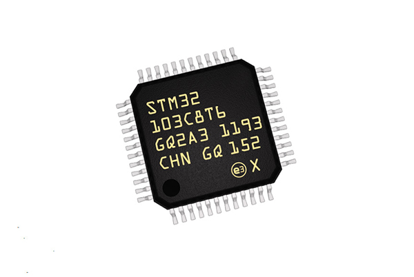
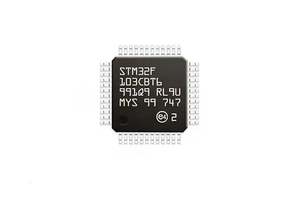
Le STM32F103C8T6 est un microcontrôleur 32 bits basé sur le cœur ARM Cortex-M3, introduit par STMicroelectronics. Il est présenté dans un boîtier LQFP48 et appartient à la ligne de performance à densité moyenne de la série STM32. Ce MCU est largement utilisé dans la conception de systèmes embarqués en raison de ses hautes performances, de sa faible consommation d'énergie et de la richesse de ses interfaces périphériques.
Paramètres de performance clés
- Architecture de l'unité centrale: Cœur RISC ARM Cortex-M3 32 bits
- Fréquence de fonctionnement: Jusqu'à 72 MHz
- Configuration de la mémoire:
- Mémoire flash de 64 Ko
- 20KB SRAM
- Plage de tension de fonctionnement2,0V à 3,6V
- Plage de température de fonctionnementTempérature de fonctionnement : -40°C à +85°C
- Type d'emballage: LQFP48 (7x7mm)
Analyse détaillée des spécifications techniques
| Catégorie | Paramètres | Valeur |
|---|---|---|
| Paramètres techniques | Fréquence | 72 MHz |
| Tension d'alimentation (DC) (min) | 2.00 V | |
| Tension de fonctionnement | 2 V ~ 3,6 V | |
| Nombre de broches | 48 | |
| Fréquence d'horloge | 72 MHz | |
| Taille de la mémoire vive | 20 KB | |
| Largeur de bit | 32 bits | |
| Capacité de la mémoire FLASH | 64 KB | |
| Nombre de canaux ADC | 2 | |
| Nombre d'E/S | 37 Entrée | |
| Température de fonctionnement maximale | 85 °C | |
| Température minimale de fonctionnement | -40 °C | |
| Tension d'alimentation (max.) | 3.6 V | |
| Tension d'alimentation (Min) | 2 V | |
| Paramètres du paquet | Type de montage | Montage en surface |
| Nombre de broches | 48 | |
| Type d'emballage | LQFP-48 | |
| Dimensions | Longueur | 7,2 mm |
| Largeur | 7,2 mm | |
| Hauteur | 1,45 mm | |
| Paramètres physiques | Température de fonctionnement | -40 °C ~ 85 °C (TA) |
| Autres informations | Cycle de vie des produits | Actif |
| Emballage | Plateau | |
| Applications | Industrie, Vidéo et imagerie, Électronique grand public, Conception et développement embarqués, Entraînement et contrôle de moteurs, Médical, Appareils portables | |
| Normes de conformité | RoHS | Conforme à la loi |
| Sans plomb | Oui | |
| REACH SVHC | Pas de SVHC | |
| Informations douanières | Code ECCN | 3A991A2 |
| Licence d'importation/exportation de Hong Kong | NLR |
Noyau du processeur et performances
Le STM32F103C8T6 est doté d'un cœur Cortex-M3 avec un jeu d'instructions Thumb-2, offrant un excellent équilibre entre performance et densité de code :
- 1,25 DMIPS/MHz de performance
- Multiplication à cycle unique et division matérielle
- Contrôleur d'interruption vectoriel imbriqué (NVIC) pour une gestion des interruptions à faible latence
- Prise en charge des opérations en bande binaire permettant la manipulation atomique des bits
Système de mémoire
Mémoire flash:
- Capacité de 64 Ko pour le stockage du code de programme
- Prise en charge de la programmation dans le système (ISP) et de la programmation dans l'application (IAP)
- Endurance de 10 000 cycles d'effacement/écriture
SRAM:
- SRAM principale de 20 Ko
- Accès à l'état d'attente zéro à 72 MHz
Fonctionnalités de gestion de l'énergie
Le STM32F103C8T6 offre plusieurs modes d'alimentation pour une consommation optimisée :
- Mode de fonctionnement: Fonctionnalité complète avec toutes les horloges actives
- Mode veille: L'unité centrale est arrêtée alors que les périphériques restent opérationnels
- Mode arrêt: Toutes les horloges sont arrêtées et le contenu des registres est conservé
- Mode veille: Consommation d'énergie la plus faible, seuls le domaine de sauvegarde et les circuits de secours étant alimentés.
Système d'horloge
L'architecture flexible de l'horloge comprend
- Oscillateur RC interne de 8 MHz (HSI)
- Oscillateur à cristal externe 4-16MHz (HSE)
- Oscillateur RC interne de 40 kHz (LSI)
- Oscillateur à cristal externe de 32,768 kHz (LSE)
- PLL programmable pour horloge système jusqu'à 72MHz
Interfaces périphériques riches
Périphériques analogiques
- CDA:
- Deux convertisseurs analogique-numérique 12 bits
- Temps de conversion de 1μs
- Jusqu'à 16 canaux d'entrée (12 externes + 4 internes)
- Prise en charge des modes simple/continu/balayage/discontinu
- Capteur de température:
- Capteur de température interne intégré
- Lisible par le canal 16 de l'ADC
Système de minuterie
- Minuterie de contrôle avancé (TIM1):
- Compteur ascendant/descendant 16 bits
- 4 canaux indépendants
- Sortie PWM avec insertion de temps mort
- Particulièrement adapté aux applications de contrôle des moteurs
- Temporisateurs d'usage général (TIM2-TIM4):
- Trois temporisateurs de 16 bits
- Prise en charge de la capture d'entrée/comparaison de sortie/génération de MWM
- Minuterie système (SysTick):
- Compteur descendant 24 bits
- Dédié à l'ordonnancement des tâches du système d'exploitation
- Chronomètres de surveillance:
- chien de garde indépendant (IWDG) piloté par une horloge dédiée à basse vitesse
- Window Watchdog (WWDG) pour la détection des anomalies logicielles
Interfaces de communication
- USART:
- Trois émetteurs-récepteurs universels synchrones/asynchrones en duplex intégral
- Prise en charge des modes LIN, IrDA et carte à puce
- Vitesse jusqu'à 4,5 Mbps
- SPI:
- Deux interfaces SPI (modes maître/esclave)
- Vitesse jusqu'à 18 Mbps
- Prise en charge du protocole audio I2S
- I2C:
- Deux interfaces I2C
- Prend en charge le mode standard (100kHz) et le mode rapide (400kHz)
- Compatible avec les protocoles SMBus/PMBus
- USB:
- Interface USB 2.0 à pleine vitesse (12 Mbps)
- Prise en charge du mode appareil
- PHY intégré ne nécessitant que des résistances externes
- CAN:
- Une interface active CAN 2.0B
- Prise en charge de vitesses allant jusqu'à 1 Mbps
- Convient aux applications de contrôle industriel et aux applications automobiles
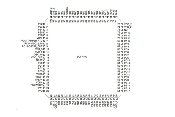
Caractéristiques GPIO
- 37 ports d'E/S rapides
- Toutes les E/S sont tolérantes à 5V (compatibles avec la logique 5V)
- Chaque E/S peut être configurée comme suit
- Entrée flottante/multipliée/multipliée/dépendante
- Entrée analogique
- Sortie à drain ouvert/push-pull
- Entrée/sortie de fonction alternative
- Vitesse de basculement jusqu'à 50 MHz
Environnement de développement et chaîne d'outils
Outils de développement de logiciels
- Outils officiels:
- STM32CubeMX : Générateur de code d'initialisation graphique
- STM32CubeIDE : Environnement de développement intégré basé sur Eclipse
- STM32CubeProgrammer :Outil de programmation unifié
- IDE tiers:
- Keil MDK-ARM
- IAR Embedded Workbench
- Plate-formeIO
- Arduino IDE (via STM32duino)
- Outils de débogage:
- Débogueur ST-LINK/V2
- J-Link
- ULINKpro
Outils de développement de matériel
- Options de la carte de développement:
- Carte de développement officielle Nucleo-F103RB
- Carte système minimale Blue Pill
- Cartes tierces de marques telles que PointGee ou Wildfire
- Interfaces de débogage:
- SWD (Serial Wire Debug) : Interface de débogage à 2 fils (PA13, PA14)
- JTAG : interface de débogage standard à 5 fils
- Méthodes de programmation:
- Programmation de l'interface SWD (recommandée)
- Programmation série UART ISP (via les broches BOOT)
- Programmation USB DFU
Scénarios d'application typiques
Le STM32F103C8T6 est largement utilisé dans divers domaines en raison de son excellent rapport performances/prix :
- Contrôle industriel:
- Modules PLC
- Conducteurs de moteurs
- Contrôleurs IHM
- Concentrateurs de capteurs
- Électronique grand public:
- Appareils domestiques intelligents
- Périphériques de jeu
- Dispositifs portables
- Points d'extrémité IoT:
- Nœuds d'acquisition de données
- Passerelles de communication sans fil
- Dispositifs de surveillance à distance
- Électronique automobile:
- Modules de contrôle de la carrosserie
- Systèmes d'info-divertissement pour véhicules
- Équipement de diagnostic OBD-II
- Dispositifs médicaux:
- Équipement de surveillance portable
- Aides à la réadaptation
- Instruments de laboratoire
Guide de conception du système minimum
Composition du circuit de base
- Circuit d'alimentation:
- Régulateur de tension LDO 3,3V recommandé
- Ajoutez un condensateur de découplage de 0,1μF à chaque broche VDD.
- Inclure un condensateur de masse ≥10μF à l'entrée de l'alimentation principale.
- Circuit de réinitialisation:
- Résistance pull-up 10kΩ + condensateur 0.1μF
- Un bouton de réinitialisation manuelle en option
- Circuit d'horloge:
- Cristal externe de 8 MHz (capacité de charge typique de 8-20pF)
- Cristal externe de 32,768 kHz (pour RTC)
- Configuration de l'amorçage:
- Broche BOOT0 connectée à la masse via une résistance de 10kΩ
- Cavalier de sélection BOOT0 en option
L'essentiel de la conception des circuits imprimés
- Principes de présentation:
- Placer les cristaux à proximité de l'unité centrale de traitement
- Positionner les condensateurs de découplage près des broches VDD correspondantes
- Sections analogiques et numériques séparées
- Recommandations de routage:
- Garder les traces du signal d'horloge courtes et droites
- Éviter le routage parallèle des signaux analogiques et à grande vitesse
- Assurer un plan de masse solide
- Protection contre les décharges électrostatiques (ESD):
- Ajouter des diodes TVS aux interfaces externes
- Résistances en série sur les lignes de signaux sensibles
Techniques d'optimisation des performances
Optimisation du code
- Optimisation du compilateur:
- Utiliser les niveaux d'optimisation -O2 ou -O3
- Activer l'optimisation du temps de liaison (LTO)
- Utilisation correcte des fonctions en ligne
- Gestion de la mémoire:
- Exécution du code critique à partir de la SRAM
- Utiliser le DMA pour réduire la charge de travail de l'unité centrale
- Planifier correctement l'espace de stockage
- Optimisation des algorithmes:
- Utiliser la bibliothèque CMSIS-DSP pour des opérations mathématiques accélérées
- Remplacer les calculs complexes par des tableaux de consultation
- Exploiter les accélérateurs matériels (CRC, etc.)
Optimisation de la puissance
- Configuration de l'horloge:
- Activer les horloges des périphériques si nécessaire
- Ajuster dynamiquement la fréquence de l'horloge du système
- Modes de faible consommation:
- Utilisation correcte des modes Stop/Standby
- Gestion de l'horloge périphérique
- Configurer les E/S non utilisées en tant qu'entrées analogiques
- Gestion des périphériques:
- Mettre hors tension les périphériques non utilisés
- Traiter les données par lots pour réduire les réveils
- Utiliser des minuteries à faible consommation d'énergie pour le réveil
Problèmes courants et solutions
Problèmes de démarrage
- Défaut de démarrage:
- Vérifier la configuration de la broche BOOT
- Vérifier la stabilité de l'alimentation électrique
- Confirmer la fonctionnalité du circuit de réinitialisation
- Le programme ne fonctionne pas:
- Vérifier l'adresse de la table vectorielle
- Vérifier la configuration de l'horloge
- Veiller à l'initialisation correcte du pointeur de pile
Questions périphériques
- Anomalies GPIO:
- Confirmation de l'activation de l'horloge
- Vérifier la cartographie des fonctions alternatives
- Vérifier la configuration pull-up/pull-down
- Défauts de communication:
- Vérifier la configuration du débit en bauds/de l'horloge
- Vérifier les connexions de la couche physique
- Assurer la concordance des niveaux de signal
- Bruit ADC:
- Ajouter les condensateurs de filtrage appropriés
- Optimiser l'agencement des circuits imprimés
- Mettre en œuvre des algorithmes de filtrage logiciel
Écosystème et ressources
Ressources officielles
- Documentation:
- Manuel de référence (RM0008)
- Fiche technique
- Notes d'application (AN)
- Bibliothèques de logiciels:
- Bibliothèque périphérique standard (SPL)
- Couche d'abstraction matérielle (HAL)
- Pilotes de la couche basse (LL)
- Outils de développement:
- Outil de configuration STM32CubeMX
- STM32CubeProgrammer
Ressources communautaires
- Forums de développement:
- Forum communautaire ST
- Le monde de l'EE
- Réseau électronique 21ic
- Projets Open Source:
- Noyau Arduino pour STM32
- libopencm3
- ChibiOS/RT
- Plateformes d'apprentissage:
- Formation officielle ST
- Cours Udemy/MOOC
- Vidéos techniques Bilibili
Sélection et solutions alternatives
Options de mise à niveau de la même série
- Capacité de mémoire plus élevée:
- STM32F103RBT6 (128KB Flash)
- STM32F103VET6 (512KB Flash)
- Plus de périphériques:
- STM32F103ZET6 (144 broches)
- STM32F103RCT6 (avec FSMC)
Alternatives de nouvelle génération
- Cortex-M4 Core:
- STM32F303C8T6 (avec FPU)
- STM32F401CCU6
- Des coûts plus élevés:
- STM32G030C8T6
- STM32F030C8T6
- Intégration sans fil:
- STM32WB55CGU6 (Bluetooth 5.0)
- STM32WL55CCU6 (LoRa)
Conclusion
En tant que microcontrôleur Cortex-M3 classique, le STM32F103C8T6 occupe une place importante dans le domaine de l'embarqué grâce à ses performances équilibrées, à la richesse de ses périphériques et à son écosystème mature. Il s'agit là d'un choix extrêmement précieux. Au fur et à mesure que la technologie évolue, ST a introduit de nouveaux modèles pour répondre à différents besoins, mais la série F103 conservera sa position sur le marché pendant un certain temps encore en raison de sa stabilité et de son support étendu.