Una delle maggiori sfide nella progettazione dell'hardware per il 2025 è trovare un equilibrio ottimale tra prestazioni, affidabilità e costi. Il substrato, che funge da scheletro e mezzo isolante del PCB, determina direttamente l'integrità del segnale, l'efficienza energetica e la competitività del prodotto finale attraverso la sua Costante dielettrica (Dk) nonché Fattore di dissipazione (Df). Una scelta inadeguata può portare a problemi che vanno dalla distorsione del segnale e dal mancato raggiungimento degli obiettivi di prestazione a problemi gravi come il surriscaldamento e i guasti di affidabilità, con conseguenti costi di rilavorazione significativi e danni al marchio.
Indice per materie
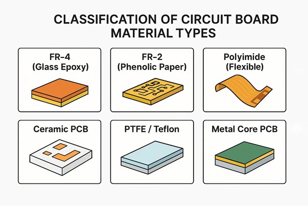
Analisi completa dei tre substrati chiave
1. FR-4: Il "tuttofare" in evoluzione
L'FR-4 non è un singolo materiale, ma una famiglia di materiali. Entro il 2025, questa famiglia si amplierà notevolmente.
- Profilo delle prestazioni
- Standard Dk/Df: Dk ~ 4,2-4,8, Df ~ 0,015-0,025
- Varianti a media perdita / bassa perdita: Attraverso resine epossidiche modificate, FR-4 a bassa perdita può raggiungere una Df di ~0,008, si avvicina ad alcuni materiali in PTFE a basso costo.
- Affidabilità termica: Le varianti ad alta Tg (temperatura di transizione vetrosa > 170°C) e prive di alogeni sono diventate lo standard per l'elettronica automobilistica e il controllo industriale.
- Scenari applicativi principali:
- Elettronica di consumo (schede madri per smartphone, computer portatili)
- Controllo industriale, moduli di potenza (utilizzando FR-4 ad alta Tg)
- Sistemi di infotainment per autoveicoli e alcune unità di controllo della carrozzeria
- Circuiti digitali sensibili ai costi in cui le velocità di segnale sono tipicamente < 5 Gbps
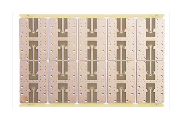
2. PTFE: il "Gold Standard" per i segnali RF ad alta velocità
Il politetrafluoroetilene (PTFE) offre le migliori prestazioni ad alta frequenza tra i substrati organici, ma il suo costo elevato e i requisiti di lavorazione specializzati spesso scoraggiano i progettisti.
- Profilo delle prestazioni:
- Df estremamente bassa: Può essere inferiore a 0,0005 - 0,002, ovvero da 1/10 a 1/50 rispetto a FR-4, riducendo drasticamente la perdita dielettrica nei segnali ad alta velocità.
- Stabile Dk: In genere tra 2,0-3,0, con variazioni minime sulla frequenza, fondamentali per mantenere stabile l'impedenza.
- Sfide di elaborazione: Il PTFE è morbido e ha un elevato coefficiente di espansione termica (CTE), il che richiede attrezzature e processi specializzati per foratura, laminazione e metallizzazione dei fori, aumentando i costi di lavorazione di circa 30%-100%.
- Scenari applicativi principali:
- Radar a onde millimetriche (per il settore automobilistico, stazioni base 5G)
- Antenne ad alta frequenza (ad esempio, comunicazioni satellitari, aerospaziali)
- Apparecchiature di rete ad altissima velocità (ad esempio, moduli ottici 400G/800G, canali SerDes superiori a 112 Gbps)
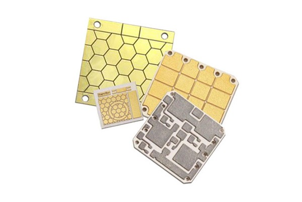
3. Substrati ceramici: La "soluzione definitiva" per potenze elevate e ambienti gravosi
Le ceramiche (ad esempio, Al₂O₃, AlN, BeO) offrono una conducibilità termica e una stabilità ambientale senza pari.
- Profilo delle prestazioni:
- Eccezionale conduttività termica (TC): Allumina (Al₂O₃) ~20-30 W/mK, Nitruro di alluminio (AlN) ~150-200 W/mK (centinaia di volte superiore a quello dell'FR-4).
- Coefficiente di espansione termica (CTE) abbinato: Si avvicina al CTE dei chip di silicio, migliorando in modo significativo l'affidabilità dei moduli di potenza in caso di cicli termici.
- Fragilità intrinseca e costi elevati: Le tavole sono fragili, le dimensioni sono limitate e i costi di lavorazione sono molto elevati.
- Scenari applicativi principali:
- Illuminazione a LED e laser ad alta potenza (LD)
- Moduli di potenza per veicoli elettrici (IGBT, SiC, GaN)
- Componenti RF ad alta potenza nell'elettronica aerospaziale e militare
Il quadro decisionale del 2025
Al momento della decisione, rispondete a queste tre domande in sequenza:
- Quanto sono esigenti i requisiti di integrità del segnale (SI)?
- Chiedetevi: Qual è la velocità/frequenza del mio segnale? Qual è la perdita di segnale accettabile (perdita di inserzione)?
- Percorso decisionale:
- < 5 Gbps o sensibile alle perdite → Preferire FR-4.
- 5 - 20 Gbps → Valutare prima FR-4 a bassa perdita / a bassissima perdita. Se il budget lo consente o i margini di rendimento sono ristretti, si può prendere in considerazione materiali ibridi di PTFE a basso costo.
- > 20 Gbps o bande a onde millimetriche → PTFE o altri materiali ad alta frequenza di alto livello (ad es., idrocarburi) sono obbligatori.
- Qual è la pressione di gestione termica?
- Chiedetevi: Qual è il consumo di energia dei miei chip/componenti? Quanto sono rigidi i requisiti di temperatura di giunzione? Qual è la temperatura ambiente di funzionamento?
- Percorso decisionale:
- Densità di potenza moderata, gestibile con i dissipatori di calore → FR-4.
- Chip ad alta densità di potenza o sensibili al calore (ad esempio, GaN) → Richiede PCB con nucleo in metallo (ad esempio, alluminio) o Substrati ceramici (preferibilmente AlN).
- Qual è il vostro budget e la vostra tolleranza di produzione?
- Chiedetevi: Qual è il mio obiettivo di costo della distinta base? Il mio produttore è in grado di lavorare materiali specializzati?
- Percorso decisionale:
- Sensibile ai costi, utilizza linee SMT standard → FR-4.
- Budget sufficiente e conferma del produttore Capacità di lavorazione del PTFE (ad esempio, trattamento al plasma) → PTFE.
- Le applicazioni sono ad altissima potenza o ad alta frequenza, con priorità alle prestazioni e all'affidabilità rispetto ai costi → Substrato ceramico.
Gestione di strutture ibride e scenari atipici
Nei progetti all'avanguardia del 2025, spesso un unico materiale non è in grado di soddisfare tutti i requisiti. Strutture ibride la soluzione ottimale.
- Scenario 1: necessità di gestire segnali ad alta velocità e alta potenza
- Soluzione: Impiegati Strutture ibride FR-4/PTFE-Ceramica. Ad esempio, l'inserimento di un chip ceramico all'interno di una scheda in PTFE consente di montare i dispositivi di alimentazione direttamente sulla ceramica per la dissipazione del calore, mentre i segnali ad alta velocità viaggiano senza perdite attraverso il PTFE.
- Scenario 2: il compromesso definitivo tra costi e prestazioni
- Soluzione: uso Laminati ibridi di PTFE e FR-4. Gli strati critici che richiedono un'estrema integrità del segnale (ad esempio, gli strati esterni) utilizzano il PTFE, mentre gli strati di potenza e di segnale a bassa velocità utilizzano l'FR-4, ottenendo un perfetto equilibrio tra prestazioni e costi.
Consigli pratici: Prima di finalizzare il substrato, è fondamentale condurre una Joint Design Review (JDM) con un produttore esperto in materiali specializzati, come TopFastPCB. Possono fornire una consulenza esperta su disponibilità di materiali, resa di lavorazione e soluzioni di struttura ibrida più economicheche è un passo fondamentale per garantire il successo del lancio del vostro progetto 2025.
conclusioni
Nel 2025 non esiste un unico substrato "migliore", ma solo la scelta "più appropriata". I confini dell'FR-4 si stanno espandendo, il costo del PTFE si sta gradualmente ottimizzando e le applicazioni della ceramica si stanno ampliando. Ci auguriamo che questa guida vi aiuti a superare la complessità e a trovare l'intersezione ottimale tra prestazioni e costi per il vostro prossimo prodotto.
Domande frequenti sul substrato per PCB
A: Si tratta di una domanda critica. L'FR-4 a bassa perdita rappresenta un progresso significativo all'interno della famiglia dell'FR-4, colmando efficacemente il divario di prestazioni tra l'FR-4 standard e il PTFE.
Può sostituire il PTFE? La risposta è "Dipende dall'applicazione". Per velocità di segnale nell'intervallo 5-20 Gbps con requisiti di perdita moderati, ma non estremi (ad esempio, canali a media velocità in switch di fascia alta), l'FR-4 a bassa perdita è una scelta altamente conveniente. Tuttavia, per frequenze a onde millimetriche o canali SerDes ad altissima velocità di 112 Gbps e oltreIl Df/Dk estremamente basso e stabile del PTFE è fondamentale per l'integrità del segnale e rimane ineguagliato dall'FR-4 a bassa perdita.
Consigli per le decisioni: Non concentratevi solo sul valore della Df. È essenziale eseguire simulazioni di canale per valutarne l'idoneità rispetto agli obiettivi di budget e perdita del collegamento. Nel 2025, l'uso di FR-4 a bassa perdita per gli strati di segnale meno sensibili in un progetto ibrido con PTFE sta diventando una strategia di ottimizzazione dei costi molto diffusa.
A: Assolutamente sì. Tra "Standard FR-4" e "Premium Ceramic", c'è una serie di soluzioni ampiamente adottate:
Soluzione primaria: PCB con anima in metallo (ad esempio, IMS in alluminio). Questi dispositivi raggiungono un'efficiente conduzione termica laminando un'anima metallica (in genere alluminio) sotto lo strato del circuito FR-4. Il costo è significativamente inferiore a quello della ceramica. Il costo è significativamente inferiore a quello della ceramica, il che lo rende la scelta più diffusa per l'illuminazione a LED ad alta potenza e per i moduli di potenza per autoveicoli.
Soluzione avanzata: Dielettrici ad alta conducibilità termica. Alcuni substrati speciali (ad esempio, alcune epossidiche o poliimmidi caricate con ceramica) offrono una conducibilità termica di 1-3 W/mK. Anche se non è elevata come quella della ceramica, si tratta di un netto miglioramento rispetto all'FR-4 standard (~0,3 W/mK), pur mantenendo la lavorabilità e i vantaggi economici dei materiali organici.
La soluzione definitiva: Intarsi in ceramica localizzati. Una piccola piastrella di ceramica viene incorporata appena sotto il componente che genera più calore (ad esempio, un transistor GaN) in una scheda FR-4 o PTFE. In questo modo si ottengono prestazioni termiche "on-demand", controllando efficacemente il costo complessivo.
A: La cautela del fabbricante è un segno di professionalità, che deriva dalle proprietà fisico-chimiche molto diverse del PTFE rispetto all'FR4. Le sfide principali sono:
Forza di adesione della laminazione: Il PTFE è intrinsecamente non appiccicoso e richiede una speciale trattamento al plasma per irruvidire la superficie e ottenere una forte adesione al foglio di rame e agli altri strati.
Qualità della perforazione: Il PTFE è relativamente morbido e duttile, il che lo rende incline a striscio di trapano e bave durante la foratura, che influiscono sulla qualità della parete del foro e pongono problemi per la successiva placcatura.
Stabilità dimensionale: Il PTFE ha un elevato coefficiente di espansione termica (CTE). Il suo diverso tasso di ritiro rispetto all'FR-4 durante i cicli di laminazione multipli richiede un'accuratezza di registrazione estremamente elevata per schede multistrato ad alto numero di strati.
Per questo motivo, la comunicazione pre-produzione con un produttore esperto nella lavorazione del PTFE (come TopFastPCB) per adattare il suo processo al vostro progetto è fondamentale per il successo del progetto.
A: No, Dk è non un valore fisso. La costante dielettrica di quasi tutti i materiali varia con la frequenza, una proprietà nota come "dispersione Dk".
FR-4: Il suo valore Dk diminuisce sensibilmente con l'aumentare della frequenza; ad esempio, può scendere da 4,5 a 1GHz a 4,2 a 10GHz. Questa instabilità introduce incertezza nel controllo dell'impedenza alle alte frequenze.
PTFE/Ceramica: I loro valori Dk variano pochissimo con la frequenza, dimostrando un'elevata stabilità. Proprio per questo motivo sono indispensabili nelle applicazioni esigenti ad alta frequenza/alta velocità.
2025 Implicazioni per la progettazione: Per le simulazioni, utilizzare sempre il valore Dk fornito dal produttore, misurato nell'intervallo di frequenza desiderato, e non solo il valore a bassa frequenza o nominale.
A: Si tratta di un classico dilemma di sovraingegneria. Il nostro consiglio è: Evitare l'eccessiva ingegnerizzazione; attenersi al principio "design-for-need".
Trappola dei costi: L'uso di un substrato che supera di gran lunga le attuali esigenze di prestazioni porta direttamente a un'impennata dei costi della distinta base e può introdurre un'inutile complessità di produzione, sacrificando la competitività del prezzo del prodotto.
Rischio di iterazione della tecnologia: La tecnologia elettronica si evolve rapidamente. Il materiale di alto livello scelto oggi per "essere a prova di futuro" potrebbe essere sostituito da una tecnologia più economica l'anno prossimo.
La giusta strategia: Un approccio più saggio è quello di incorporare la possibilità di aggiornamento nel progetto iniziale. layout, instradamento, selezione dei connettori e architettura del sistema livelli. Ad esempio, anche se inizialmente si utilizza l'FR-4, è possibile pianificare i futuri cambiamenti tecnologici ottimizzando lo stack-up e riservando spazio per la schermatura. Investite il vostro budget dove crea il valore più diretto.