PCB-Board-Befestigungsmethode
Zu den wichtigsten Leiterplatten-Montagetechniken gehören mechanische Befestigung, strukturelles Klemmen und Verkapselungsmethoden.Enthält detaillierte technische Spezifikationen, Leistungsvergleiche und Auswahlhilfen, die Ingenieuren bei der Auswahl der besten Befestigungslösung auf der Grundlage von Zuverlässigkeitsanforderungen, Umgebungsbedingungen und Produktionsüberlegungen helfen.
Inhaltsübersicht
Einführung in die Leiterplattenmontage
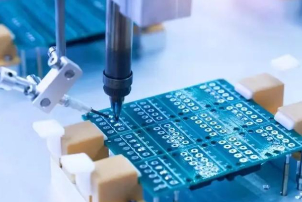
Gedruckte Leiterplatten (PCBs) dienen als Grundgerüst elektronischer Geräte, tragen verschiedene elektronische Komponenten und ermöglichen elektrische Verbindungen. Die richtige Montage und Befestigung ist nicht nur für einen stabilen Betrieb der Schaltkreise entscheidend, sondern auch für die Verbesserung der Produktlebensdauer und der Wartungsfreundlichkeit. In diesem umfassenden Leitfaden werden alle wichtigen Leiterplatten-Montagemethoden, ihre Vorteile, Grenzen und idealen Anwendungen erläutert, damit Sie fundierte Entscheidungen für Ihre elektronischen Designs treffen können.
Mechanische Befestigungsmethoden
1. Schraubmontage (am zuverlässigsten)
Technische Daten:
- Der Durchmesser des Schraubenlochs sollte den Außendurchmesser der Schraube um 0,1-0,2 mm übersteigen.
- Erfordert in der Regel die Positionierung von Säulen zur genauen Ausrichtung
- Empfohlenes Drehmoment: 0,6-1,2N-m für M2,5-M4 Schrauben
- Materialpaarung:Schrauben aus rostfreiem Stahl mit Messinggewindeeinsätzen bevorzugt
Vorteile:
- Höchste Zuverlässigkeit und Vibrationsfestigkeit
- Hervorragende Tragfähigkeit (ideal für Computer-Motherboards)
- Ermöglicht eine präzise Druckkontrolle durch Drehmomenteinstellung
Beschränkungen:
- Höhere Montagekosten und längere Installationszeit
- Benötigt Platz für Schraubendreher
- Mögliche Schäden durch zu festes Anziehen
Am besten geeignet für: Industrieausrüstung, Automobilelektronik und Geräte, die eine hohe Stoßfestigkeit erfordern
2.Schnappbefestigung (am kostengünstigsten)
Entwurfsparameter:
- Einrasttiefe ≥0,5mm
- Breite ≥3mm
- Typischerweise kombiniert mit 1-2 Schrauben für verbesserte Stabilität
- Entlastungswinkel: 30-45° für einfache Montage/Demontage
Vorteile:
- Schnelle Montage (reduziert die Produktionszeit um 20-30%)
- Eliminiert Befestigungselemente und reduziert die Stücklistenkosten
- Platzsparendes Design
Beschränkungen:
- Begrenzte Vibrationsfestigkeit
- Plastische Ermüdung über mehrere Zyklen
- Erfordert präzisen Werkzeugbau
Am besten geeignet für: Unterhaltungselektronik, IoT-Geräte und Kleingeräte
Lösungen für strukturelles Klemmen
3. Klemmen des Gehäuses
Leitlinien für die Umsetzung:
- Mindestens 3 mm Klemmbereich an den PCB-Kanten
- sollte einen Versetzungsschutz enthalten
- Empfohlen für Bretter mit einer Länge von mehr als 150 mm
Vorteile:
- Keine zusätzlichen Befestigungselemente erforderlich
- Hervorragend geeignet für Boards mit dichten Anschlüssen
- Vereinfacht den Montageprozess
Beschränkungen:
- Erfordert robustes Gehäusedesign
- Eingeschränkte Eignung für Umgebungen mit hohen Vibrationen
- Unterschiedliche Plattendicken beeinflussen die Leistung
Am besten geeignet für: Mittelgroße Steuerplatinen und schnittstellenintensive Designs
4.Blechmontage
Technische Optionen:
- PEM-Bolzen (Einpress-Gewindeeinsätze)
- Distanzsäulen (Messing oder Nylon)
- Stapelhöhentoleranz: ±0,1 mm pro Platte
Vorteile:
- Ideal für Arrangements mit mehreren Boards
- Ermöglicht konsistente Abstände von Brett zu Brett
- Ermöglicht Wärmemanagement
Beschränkungen:
- Erhöhte Komplexität der Montage
- Höhere Werkzeugkosten
- Potenzial für galvanische Korrosion
Am besten geeignet für: Industrielle Steuerungssysteme und Leistungselektronik
Verkapselung und spezielle Prozesse
5. Verguss und Verkapselung
Material-Optionen:
- Epoxidharze (Schutzart IP68)
- Silikongel (Schwingungsdämpfung)
- Polyurethan (kostengünstige Alternative)
Überlegungen zum Prozess:
- Aushärtezeit: 2-24 Stunden, je nach Material
- Erfordert Entlüftung für Ausgasung
- Topfzeit in der Regel 30-90 Minuten
Vorteile:
- Hervorragender Schutz der Umwelt
- Hervorragende Schwingungsdämpfung
- Verbessertes Wärmemanagement
Beschränkungen:
- Unumkehrbarer Prozess
- Schwierige Nacharbeiten/Reparaturen
- Zusätzliches Gewicht
Am besten geeignet für: Automobil, Luft- und Raumfahrt und Anwendungen für raue Umgebungen
6.Formteil einlegen
Prozessparameter:
- Einspritztemperatur:180-220°C
- Zykluszeit: 30-60 Sekunden
- Maximale Bauteilhöhe: 10 mm
Vorteile:
- Echte hermetische Abdichtung
- Eliminiert die sekundäre Montage
- Hervorragende Teilekonsolidierung
Beschränkungen:
- Hohe Investitionen in Werkzeuge
- Thermische Belastung der Komponenten
- Begrenzt auf einfache PCB-Designs
Am besten geeignet für: Hochvolumige Einwegelektronik und miniaturisierte Geräte
Aufkommende Montagetechnologien
7. Leitfähige Verklebung
Technische Daten:
- Blechwiderstand: <0,01Ω/sq
- Aushärtungstemperatur: 120-150°C
- Haftfestigkeit: 5-10MPa
Vorteile:
- Keine mechanische Belastung der Platten
- Ermöglicht flexible Zusammenschaltungen
- Geeignet für heterogene Integration
Beschränkungen:
- Eingeschränkte Reparierbarkeit
- Spezialisierte Ausrüstung erforderlich
- Langfristige Zuverlässigkeitsdaten sind rar
8.Integration der optischen Verbindungstechnik
Leistungsmerkmale:
- Datenraten: >25Gbps pro Kanal
- Ausrichttoleranz: ±5μm
- Einfügungsdämpfung: <1dB pro Anschluss
Vorteile:
- EMI immun
- Ultrahohe Bandbreite
- Gewichtsreduzierung
Beschränkungen:
- Nischenanwendung
- Hohe Präzision erforderlich
- Für die meisten Anwendungen unerschwinglich
Methodik der Auswahl
Entscheidungsmatrix:
| Kriterien | Schraube | Einrastbar | Gehege | Eintopfen | Einsatzform |
|---|---|---|---|---|---|
| Verlässlichkeit | ★★★★★ | ★★☆☆☆ | ★★★☆☆ | ★★★★★ | ★★★★☆ |
| Montagegeschwindigkeit | ★★☆☆☆ | ★★★★★ | ★★★★☆ | ★★☆☆☆ | ★★★★★ |
| Reparaturfähigkeit | ★★★★★ | ★★★★☆ | ★★★★☆ | ★☆☆☆☆ | ★☆☆☆☆ |
| Kosteneffizienz | ★★☆☆☆ | ★★★★★ | ★★★★☆ | ★★★☆☆ | ★★☆☆☆ |
| Platzersparnis | ★★☆☆☆ | ★★★★★ | ★★★☆☆ | ★★★★☆ | ★★★★★ |
Umweltaspekte:
- Vibration >5G: Schraube oder Verguss bevorzugt
- IP67+ Anforderungen:Vergießen oder Umspritzen
- Hochtemperatur:Schrauben mit Hochtemperatur-Kunststoffen
- Medizinische Sterilisation: Schnappverschluss mit Materialien der USP-Klasse VI
Wartung und Instandhaltung
Leitlinien für Design for Service:
- Vor Ort austauschbare Einheiten sollten mit Schrauben oder Schnappverschlüssen befestigt werden.
- Der Verguss sollte auf nicht betriebsfähige Module beschränkt werden.
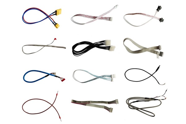
- Bereitstellung von Serviceschleifen für kabelgebundene Verbindungen
- Demontagepunkte deutlich kennzeichnen
- Berücksichtigung des Werkzeugzugangs bei der Konstruktion des Gehäuses
Verkürzung der mittleren Reparaturzeit (MTTR):
- Standardisierte Befestigungsmittel
- Farbcodierte Anschlüsse
- Merkmale der geführten Montage
- QR-Codes, die zu Servicehandbüchern führen
Zukünftige Trends in der Leiterplattenbestückung
- Intelligente Befestigungen: IoT-fähige Schrauben zur Überwachung von Vorspannung und Korrosion
- Selbstheilende Polymere: Automatische Reparatur von Einrastmerkmalen
- Nanostrukturierte Klebstoffe: Hochfeste leitfähige Verbindungen, die bei Raumtemperatur aushärten
- 4D-bedruckte Clips: Formgedächtnis-Montagemerkmale, die sich an thermische Veränderungen anpassen
- Biologisch abbaubare Halterungen: Nachhaltige Alternativen für Wegwerfelektronik
Optimieren Sie Ihre Montagestrategie
Bei der Auswahl der geeigneten Leiterplatten-Montagemethode ist Folgendes zu beachten:
- Anforderungen an den Produktlebenszyklus
- Umweltbedingungen
- Produktionsvolumen
- Erwartungen an den Service
- Kostenvorgaben
Verwandte Beiträge