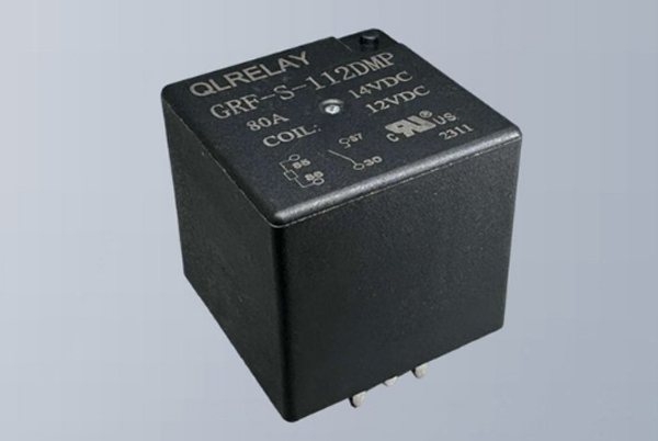
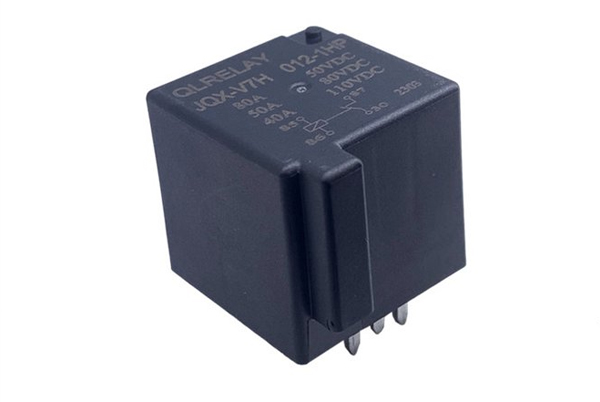
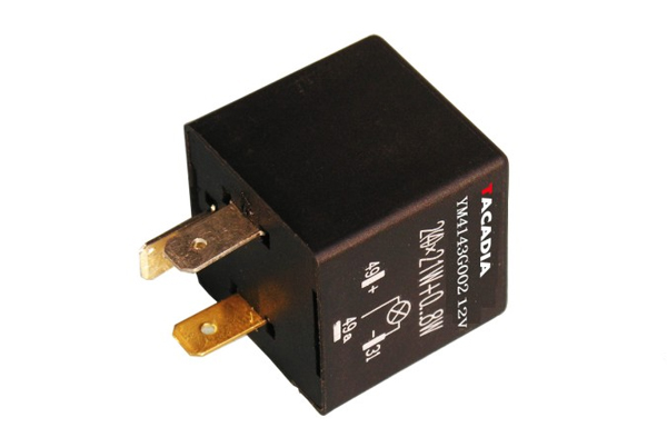
Automatic Charging Relay
Table of Contents
What is an Automatic Charging Relay
An automatic charging relay is a type of relay used to automatically control the charging process, usually in electric vehicles or other devices that require automatic charging. Its main function is to automatically cut off the charging circuit when the battery is fully charged to prevent overcharging, thus protecting the battery and prolonging its service life.
Relay (English name: relay) is a kind of electric control device, is the change of input quantity (excitation quantity) to reach the stipulated requirements in the electrical output circuit to make the controlled quantity undergo a predetermined step change in a kind of electrical appliance. It has an interactive relationship between the control system (also called the input circuit) and the controlled system (also called the output circuit). Usually used in automated control circuits, it is a kind of “automatic switch” that controls the operation of large currents with small currents. Therefore, it plays the role of automatic adjustment, safety protection, and a conversion circuit in the circuit.
Types of Automatic Charging Relays
The main types of automatic charging relays include electromagnetic relays, thermal relays, time relays, and speed relays. These relays are categorized according to their principle of action, structural feature,s and type of load.
1.Electromagnetic Relay
Electromagnetic relays are the most common type of relays that control the on-off of a circuit through electromagnetic effects. When the coil is energized, it generates a magnetic field that attracts the iron core, causing the contacts to close or break, thus realizing the control of the circuit.
Main functions: the control circuit and load circuit are completely isolated to improve safety, can control high current or high voltage circuits, simple mechanical structure, and long life. If you need to select the type, you need to consider the voltage, current, contact type, and other parameters to ensure the best performance.
2.Thermal Relay
Thermal relay is a commonly used electrical protection device, which is mainly used to prevent motor or electrical equipment from being damaged due to overload. When the current in the circuit exceeds the set value, the thermal element heats up and bends and deforms the bimetal, which triggers the mechanical mechanism to disconnect the circuit and ensure the safety of the equipment.
Main function: precise overload protection, simple and reliable structure with strong anti-interference ability. The action current can be adjusted according to the demand of equipment, not directly cut off the main circuit, only control the contactor coil, high security.
3.Time relay
Time relay is a kind of control device with a time delay function, which can automatically connect or disconnect the circuit after a set time, and is widely used in automation system that needs precise time control.
Main function: precise control to meet different needs. Can be matched with contactors, PLC, etc. to realize complex timing control, electronic high precision, and to adapt to different environments.
4.Speed Relay
Speed relay (also known as speed relay) is a kind of automation component used for detecting the speed of motor or rotating equipment, which can automatically turn on or off the control circuit according to the preset speed value, and is widely used in motor speed regulation, braking control, and equipment protection system.
Main functions: prevent motor damage due to overspeed or low-speed blocking, with an inverter to realize closed-loop speed regulation, non-contact electronic anti-vibration, maintenance-free, suitable for harsh environments.
Relay Circuit Symbols
1.Circuit representation of relay coils
A standardized representation of relay coils is used in circuit diagrams:
Basic symbol: A single coil is represented using a long box graphic
Double coil representation: When a relay has two coils, two long boxes are drawn side by side.
Labeling norms: The text symbol “J” (from the pinyin initials of “relay”) must be labeled inside or next to the long box.
2.Two ways of drawing relay contacts
Centralized drawing method
Characteristics: All contacts are drawn on the same side of the long box representing the coil.
Advantage: Visualize the complete structure of the relay
Applicable scenarios: simple circuit design, teaching schematic diagrams.
Decentralized drawing method
Characteristics: According to the actual circuit needs, the contacts will be scattered in different positions.
Labeling requirements:
Ensure that the coil and the corresponding contacts use the same symbol (e.g. J1).
Add a number to each contact group (e.g. J1-1, J1-2)
Advantage: Makes the wiring of complex circuits clearer and easier to read.
3.Three types of relay contacts
1. Normally open contacts (type H)
Symbol identification: indicated by the letter “H”.
When the coil is de-energized, the contact remains open:
When the coil is de-energized, the contact remains open.
When the coil is energized, the contact closes and conducts.
Typical applications: circuit start-up control, equipment energized switching.
2.Normally closed contact (D type)
Symbol identification: indicated by the letter “D”.
Symbolization: The letter “D” is used to indicate the operating characteristics:
When the coil is de-energized, the contact remains closed.
When the coil is energized: the contact is open
Typical applications: safety protection circuits, emergency stops.
3.Change-over contact (Z type)
Symbol identification: indicated by the letter “Z”.
Structural features:
Contains 3 contacts: 1 movable contact + 2 static contacts.
Form two contact pairs
Operating characteristics:
When the coil is not energized, the movable contact is closed to one of the static contacts and disconnected from the other.
When the coil is energized, the position of the movable contact is switched to change the connection state.
Typical applications: circuit switching control, motor forward and reverse control.
Automatic charging relay function
1.Intelligent charging management and precise on-off control
Automatic charging relay plays a key role in the field of power control, and its excellent on-off performance provides a solid guarantee for charging safety. Taking the electric vehicle charging pile as an example, the relay system can
Precise control: Achieve ma illisecond response to ensure stable power on when charging is initiated.
Safe disconnection: Reliable disconnection of the circuit when charging is completed or under abnormal conditions.
Mode switching: Intelligent switching of fast/slow charging modes according to the control instructions, supporting advanced functions such as charging reservation.
Efficiency optimization: significantly improve energy utilization efficiency by dynamically adjusting charging parameters.
2.Multiple circuit protection mechanisms
The modern automatic charging relay integrates a full range of protection functions, building multiple safety barriers for the charging system:
Core protection function:
Over-current protection: real-time monitoring of the current, beyond the safety threshold, cuts off immediately
Over-voltage protection: automatic disconnection in case of abnormal grid voltage
Power failure protection: Responding to sudden power failure to ensure the safety of the equipment
Temperature monitoring: prevent equipment damage caused by overheating
Protection Advantage:
Response time <20ms, far exceeding mechanical switches
Programmable protection parameters, adapting to different equipment needs
Failure self-diagnosis function, improve maintenance efficiency
3.Intelligent monitoring and remote control system
As the core component of the intelligent charging system, the automatic charging relay has a strong data interaction capability:
Monitoring function:
Real-time collection of key parameters such as charging current, voltage, temperature, etc.
Data sampling accuracy of ± 0.5%, to ensure the accuracy of monitoring
Instant alarm for abnormal status, supporting a hierarchical warning mechanism.
Control features:
Support 4G/5G/WiFi and other communication protocols.
Remote start/stop, mode switching, and other operations can be realized.
Cooperate withthe cloud platform to realize charging pile cluster management.
Open API interface for system integration
Through these three core functions, the automatic charging relay not only guarantees the safety and reliability of the charging process but also promotes the development of the charging infrastructure in the direction of intelligence and networking, and provides key technical support for power management in the new energy era.
Automatic charging relay working principle
Automatic charging relay is a kind of intelligent control device based on electromagnetic principles, and its core function is to realize the automatic on-off control of the charging circuit. The following is its detailed working principle:
1.Charging start-up phase
When the charging process starts
The control system applies a working voltage to the electromagnetic coil of the relay, which generates a strong electromagnetic field after being energized. The electromagnetic force overcomes the spring resistance and attracts the armature to act, and the movable and static contacts are closed reliably to form the charging circuit.
2.Charging Holding Stage
In the normal charging process
The electromagnetic coil is continuously energized to maintain the magnetic field, and the contacts are kept closed to ensure stable current transmission and the control system monitors the charging parameters (voltage, current, temperature, etc.) in real time.
3.Charging termination stage
When the charging completion signal is detected
The control system cuts off the power supply to the electromagnetic coil, the electromagnetic field disappears rapidly, the spring mechanism pushes the armature to reset, the movable contact and the static contact are separated quickly, and the circuit is completely disconnected.
This intelligent on-off control not only ensures the safety and reliability of the charging process but also effectively extends the service life of the battery, which is an indispensable key component in modern charging equipment.
Advantages and disadvantages of automatic charging relays
1.Advantages
Automatic control: can automatically detect the battery status and cut off the charging circuit, reducing manual intervention.
Battery protection: prevent overcharging and over-discharging, prolong the service life of the battery.
Safe and reliable: reduce safety accidents caused by improper charging.
2.Disadvantages
Higher cost: Compared with ordinary chargers, automatic charging relays increase the complexity and cost of the system.
Complex maintenance: requires regular inspection and maintenance of the relay and its control system.
Application of automatic charging relays on PCBs
1.Expanding the control range
Automatic charging relay can control the data signal through multiple points of contact, to ensure that a certain value, you can press the point of contact group of different methods, in addition to replacing, opening, and closing, connecting multiple circuits.
2.Increase load capacity
Automatic charging relay can use a very small amount of control, control a large output power circuit. For example, dexterous relays and intermediate relays can control high-power supply circuits with a small amount of control.
3.Integrated Data Signal
When multiple control data signals are input to a multi-winding relay in the required manner, it can undergo comparative integrated type processing to ensure the desired control effect.
Automation control: Automatic charging relays can be formed with other electrical products to operate program control lines for automation control. For example, relays on protection equipment can be combined with other electrical products to form an operation program control line for automated control operation.
Automatic charging relay in PCB design considerations
1.Select the right relay model
Select the right 5V relay module according to load capacity, response time, and life time, etc. 5V relay modules are widely used in automation control, smart home, industrial production line, and other fields due to their moderate voltage and direct compatibility with most microcontrollers.
2.Design the control circuit of the relay
The control circuit of a relay involves signal input, processing, and output. The input side can receive signals from various control devices, such as the GPIO output of the microcontroller, sensor signals, and so on. The outputs are then connected to the load circuit being controlled. The control terminal is usually part of the relay coil. When the control terminal is driven by an appropriate voltage, the coil generates a magnetic field, which in turn causes the relay to operate.
3.Optimize solenoid coil design
The solenoid coil is one of the core components of the relay, and its design needs to ensure that the electromagnetic force generated by the coil when it is energized is sufficient to drive the mechanical structure while minimizing energy consumption.
Ensure a reliable electrical connection: In PCB design, contacts are connected to various parts of the circuit through holes in the PCB board, a connection that is not only convenient but also provides a reliable electrical connection.
Application areas of automatic charging relay
1.New Energy Vehicles
In new energy vehicles, the automatic charging relay is mainly used to control the switching of the battery pack, motor, charging port, and other components. Specifically, it can control the on-off of the circuit, to realize the functions of starting, accelerating, decelerating, and stopping of the vehicle. In addition, when the vehicle is charging, the automatic charging relay can also control the switch of the charging port to ensure the safety and stability of the charging process.
2.Charging gun and charging post
Relays also play an important role in charging guns and charging piles. For example, Hongfa’s HF161F relay is widely used in charging guns and charging piles to control the on-off of the circuit. Another Hongfa HF179F relay is used to control the on-off of the circuit to ensure the safe operation of the charging equipment. In addition, Aohi’s 3.5/4kW intelligent charging and discharging guns also have built-in relays to provide a variety of protection functions, such as over-voltage protection and over-current protection.
3.Solar Power Generation System
In a solar power system, the automatic charging relay can control the switch of the solar panel and protect the circuit to prevent the panel from being damaged by too much or too little current. At the same time, the relay can also be used in conjunction with the solar controller to realize the intelligent management of the solar power generation system.
Frequently asked questions about automatic charging relays
1.Relay fails to engage (does not work)
Possible causes:
Insufficient supply voltage (coil voltage does not match).
Control signal failure (e.g. microcontroller does not output a signal).
The relay coil is broken or aging.
Poor wire contact (e.g., loose terminals, oxidation).
Solution:
Check whether the rated voltage of the coil matches the input (e.g,. 12V/24V).
Measure the control signal with a multimeter to see if it is normal.
Test the coil on/off, infinite resistance needs to be replaced.
Clean the terminals and retighten the connecting wires.
2.Relay is engaged but charging abnormally
Possible causes:
Contact resistance is too high due to contact ablation or oxidation.
Load current exceeds relay rating (e.g. battery short circuit or overload).
Charging control logic error (such as voltage detection is not allowed).
Solution:
Check if the contacts are blackened or pitted and replace if necessary.
Confirm the load current and select a higher specification relay (e.g. 30A instead of 10A).
Check voltage sensor or charge controller settings.
3.Relay continues to engage/fails to disengage
Possible causes:
Control signal stuck (e.g. program bug or relay drive circuit failure).
Contacts sticking (high current leads to fusion welding).
Mechanical structure stuck (dust or wear).
Solution:
Disconnect the control signal and observe if it releases; check the drive transistor / MOSFET.
Replace the relay and troubleshoot the cause of the overcurrent (e.g., reverse battery).
Clean or replace mechanical parts.
4.Severe relay heating
Possible causes:
Increased resistance due to poor contact.
Prolonged overload operation.
Poor heat dissipation conditions (e.g., confined space).
Solution:
Measure the contact voltage drop and replace it when abnormally hot.
Increase relay current margin (e.g. use automotive grade relays).
Improve ventilation or install a heat sink.
5.Coil burnout
Possible causes:
Input voltage is too high (e.g. 24V mistakenly connected to 12V coil).
Coil short circuit (insulation broken).
Overheating due to frequent switching.
Solution:
Check the voltage specification and add an over-voltage protection circuit (e.g. voltage regulator diode).
Replace the relay and check the wiring insulation.
Reduce the switching frequency or select a solid-state relay (SSR).
6.Noise or vibration
Possible causes:
Coil voltage fluctuation (e.g., unstable PWM signal).
Installation is not secure.
AC relay used for DC scenario (or vice versa).
Solution:
Ensure that the voltage is smooth and add filter capacitors if necessary.
Reinforce the mounting bracket or use anti-vibration pads.
Select a DC-specific relay (DC coil).
7.Malfunction (random on-off)
Possible causes:
Electromagnetic interference (e.g., nearby motor, inverter).
Control signal interference (e.g,. long wires not shielded).
High ambient humidity leads to leakage.
Solution:
Connect the relay coil in parallel with a current-continuing diode.
Use shielded wires and keep away from interference sources.
Select the moisture-proof model or do a triple-proof treatment.


Related Posts