Common Compenents On A PCBA
Table of Contents
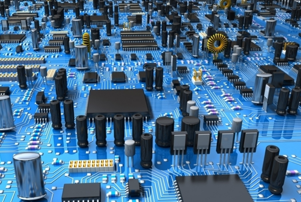
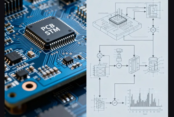
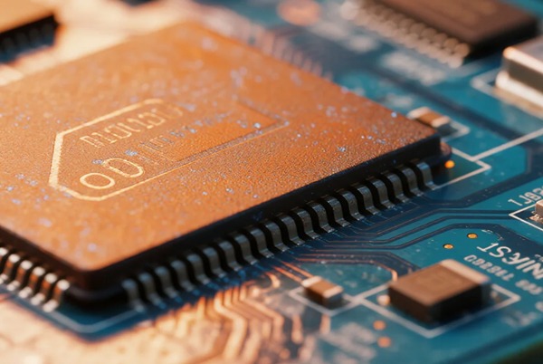
What is PCBA
The full name of PCBA is Printed Circuit Board Assembly, i.e. Printed Circuit Board Assembly, which refers to the assembly of electronic components, connectors, plug-ins, digital logic gates, micro-control units, etc. onto a printed circuit board, and then a variety of processes such as soldering and plugging to make it a complete functional module of an electronic product.
What are the common components on the PCB
1.Passive components
- Resistors (Resistor)
Function: Limit the current size, voltage shunt
Common types: carbon film resistors (economical and practical), metal film resistors (higher precision), wirewound resistors (high-power applications), chip resistors (SMD, modern mainstream)
Identification techniques: color ring code: 4-6 color rings to indicate the resistance value and accuracy, chip code: 3-4 digits to indicate the resistance value
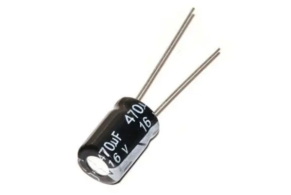
Circuit Symbol: Rectangular box or wavy line - Capacitor (Capacitor)
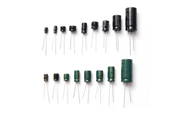
Function: energy storage, filtering, coupling
Mainstream types: electrolytic capacitors (large capacity, polarity), ceramic capacitors (good high frequency characteristics), tantalum capacitors (small size, high stability), film capacitors (high precision)
Circuit marking: “C” beginning (such as C1, C2)
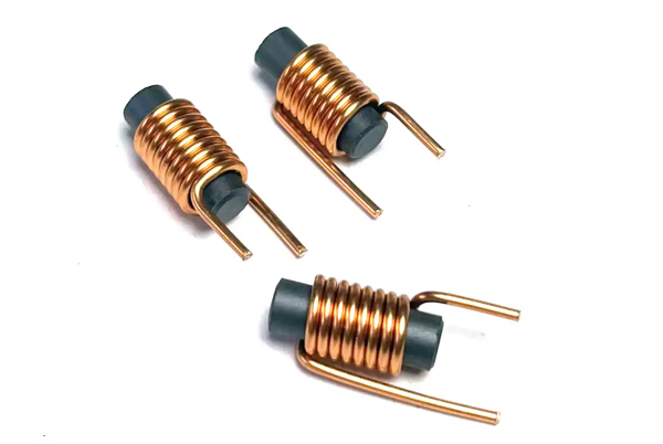
Selection points: capacitance value, withstand voltage value, temperature coefficient - Inductor (Inductor)
Function: filtering, energy storage, current stabilization
Main categories: hollow inductors (high-frequency applications), ferrite inductors (anti-interference), chip inductors (space-saving), power inductors (high-current)
Circuit marking: “L” beginning (such as L1, L2)
2.Semiconductor devices
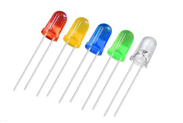
- Diode (Diode)
Function: unidirectional conductivity, voltage stabilization, light-emitting
Common types: rectifier diodes (such as 1N4007), voltage regulator diodes (such as 1N4742), Schottky diode (low drop), LED (light-emitting diode), TVS diodes (anti-static)
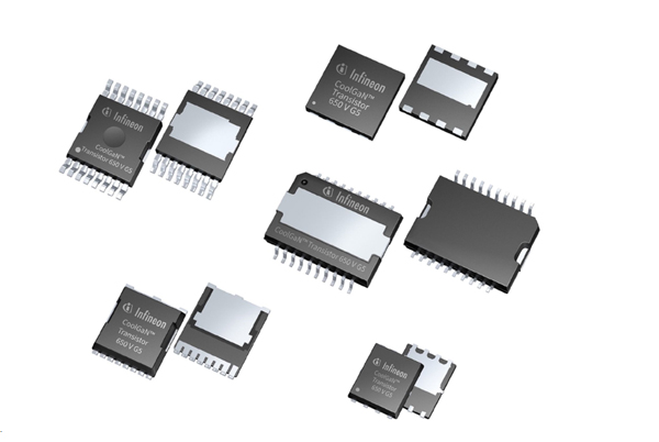
Circuit marking: “D” beginning - Transistor (Transistor)
Function: signal amplification, switching control
Main types: transistor (BJT), field effect tube (MOSFET), IGBT (high-power switch)
Package: TO-92 (low power), TO-220 (medium power), SOT-23 (SMD)
3.Integrated Circuits
- Analog IC
Operational amplifiers, voltage regulators, data converters (ADC/DAC) - Digital ICs
Microcontroller (MCU)
Memory (Flash, RAM), logic gate circuits - Mixed-signal ICs
Wireless transceiver chips, sensor interface ICs
4.Other Important Components
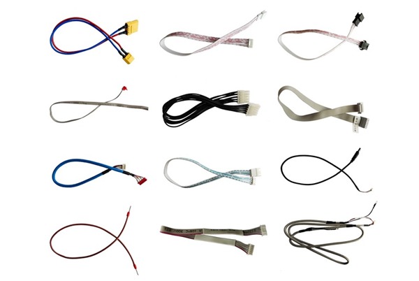
- Connectors
Pin header/female connector, USB/HDMI interface, board-to-board connector - Protection components
Fuses, varistors, gas discharge tubes - Electromechanical components
Relay, switch, buzzer
What certifications are required for components
Specific certification requirements for different types of components
Integrated circuits: ISO/IEC 27001 Information Security Management System certification is required to ensure that the design and manufacture comply with the relevant standards.
Capacitors and resistors: RoHS certification is required to ensure that they do not contain hazardous substances.
Connectors: UL certification or other electrical safety certification is required to ensure safety during use.
LED components: Safety and performance certifications are required to ensure compliance in lighting and display applications.
Semiconductor devices: need to be AEC-Q100 certified for use in automotive electronics.
Sensors: industry-specific certifications may be required, such as ISO 13485 for medical electronics
These certifications not only ensure the quality and safety of the product, but also help the product to be compliant in the marketplace.
The role of common components on the PCB
1.Resistor (Resistor)
Core functions: current limiting, voltage distribution, signal regulation
Typical applications: provide the appropriate bias voltage for the transistor, in the sensor circuit to adjust the signal level, as a current-limiting LED protection components
2.Capacitor
Core functions: energy storage, noise filtering, signal coupling
Typical applications: power supply circuit filtering (to eliminate ripple), signal coupling in audio circuits, digital IC power pin decoupling
3.Inductor
Core functions: energy storage, high-frequency filtering, current stabilization
Typical applications: switching power supply energy conversion, impedance matching in RF circuits, the key components of EMI filters
4.Diode (Diode)
Core functions: one-way conductivity, voltage regulation, circuit protection
Typical applications: AC to DC rectifier circuit, over-voltage protection TVS diode, to prevent the power reverse protection circuit
5.Transistor (Transistor)
Core functions: signal amplification, electronic switching, current control
Typical applications: audio signal amplification, digital logic circuits, motor drive control
6.Integrated Circuit (IC)
Core functions: realization of complex electronic functions
Typical applications: microcontrollers (system control core), operational amplifiers (signal processing), power management ICs
7.Electromechanical components
Switches: circuit on/off control
Connectors: electrical connection between modules
Relay: small current to control large current
Indication and alarm components
LED: visual indication of working status
Buzzer: audible alarm indication
8.Protection Components
Fuse: overcurrent protection
Varistor: Surge protection
Gas discharge tube: lightning protection
9.Sensor Components
Temperature sensor: environmental monitoring
Photoresistor: Light intensity detection
Accelerometer: Motion sensing
How to quickly identify PCB components
Look at the marking: letters + numbers next to the component numbering
Look at the package: different components have a typical package form
Measurement parameters: using a multimeter to measure the basic characteristics of the
Check the information: according to the model query specifications
PCB on the common component symbols
PCB on the common component symbols include resistance (R), capacitance (C), inductance (L), integrated circuits (IC), diodes (D), transistors (Q), transformers (T) and so on.
Character Circuit Diagram Symbols
1.Basic electrical symbols
- Power supply category
AC: alternating current symbol (wavy line)
DC: direct current symbol (straight line + dotted line)
G: generator symbol (circle with G) - Protective devices
FU: Fuse (rectangular center break)
FF: Falling fuse (rectangle with slash)
FV: Voltage limiting protection device (rectangle with arrow)
2.Control device symbols
- Switch category
QS: Disconnecting switch (slash disconnect)
QF: Circuit breaker (with trip symbol)
SB: Push-button switch (half-circle connection) - Relays
KA: Instantaneous relay (with lightning in the box)
KT: Time relay (with clock in the box)
KH: Thermal relay (with wavy lines in the box)
3.Measuring Instrument Symbols
- Basic meter
PA: ammeter (A in circle)
PV: Voltmeter (V in circle)
PPF: Power factor meter (cosφ in circle) - Electricity measurement
PJ: Active meter (Wh in circle)
PJR: reactive power meter (VARh in circle)
4.Motor and actuator
- Electric motor
M: General symbol for electric motor (M in circle)
MS: Synchronous motor (double circle)
MA: Asynchronous motor (with slash in circle) - Actuator
YV: Solenoid valve (rectangle with wavy line)
YM: Motorized valve (rectangle with gear)
YE: electric actuator (rectangle with arrow)
5.Signal indicating device
- Indicator light
HR: red light (solid circle with H)
HG: green light (solid circle with G)
HY: Yellow light (solid circle with Y) - Signaling device
HA: Acoustic signal (horn symbol)
HS: Light signal (lightning symbol)
HP: Light sign (rectangle with text inside)
6.Special Component Symbols
- Sensor type
BL: Liquid level sensor (trapezoidal with wavy lines)
BT: Temperature sensor (rectangle with thermometer)
BV: speed sensor (rectangle with tachometer) - Power electronics
UR: Thyristor rectifier (triangular with gate)
UI: Inverter (rectangle with bidirectional arrow)
UF: Inverter (rectangle with frequency symbol)
7.Wiring and connecting devices
- Connection devices
XT: Terminal block (circular arrangement of points)
XB: Connection tabs (rectangular connecting wires)
XP/XS: plug socket (concave butt symbol) - Busbar system
W: DC busbar (thick solid wire)
WV: voltage mini-busbar (dotted line)
WCL: closing small busbar (with switch symbol)
Mastering these symbols is the basis for understanding circuit schematics, and with experience, you will be able to quickly interpret a variety of complex electrical drawings.
PCB component layout and wiring design
1.Basic principles of component layout
- Strategic Priority Layout
First arrange the core IC and large components (such as processors, FPGA)
Then arrange key peripheral circuits (clock circuits, power modules)
Finally arrange small passive components (resistors, capacitors, etc.) - Signal flow optimization layout
According to the schematic signal flow direction (input → processing → output) sequence layout
Critical signal paths are minimized (especially for high-speed signals)
Sensitive signals away from interference sources (e.g. switching power supply) - Symmetry aesthetics and functional balance
Mirror symmetry layout for the same functional modules
Uniform distribution of components on the board (to avoid weight skew)
Balanced heat dissipation and electromagnetic compatibility.
2.Professional layout details
- Functional modular layout
Strict partitioning of digital/analog circuits (recommended spacing >5mm)
Separate isolation for RF circuits
Centralized arrangement of power supply modules - Safety spacing specification
Components from the board edge ≥ 5mm (to prevent processing damage)
Between the chip components ≥ 2mm (easy to repair)
Between high-voltage components ≥ 8mm (safety requirements) - Special component processing
Heat generating components:
Uniform distribution to avoid hot spot concentration
Keep away from heat-sensitive components (such as electrolytic capacitors)
Add heat sinks if necessary
High frequency components:
As close to the center of the board as possible
Keep away from I/O ports
Use ground shield protection - Decoupling capacitor arrangement
0.1μF capacitor on each power pin
Layout distance <3mm (ideally mounted on the backside)
When multiple capacitors are connected in parallel, they are arranged from smallest to largest capacity.
3.Intelligent wiring strategy
- Prioritize key signals
Clock signals:
Thicker line width (usually 8-12 mil)
Full accompanying ground
Avoid right-angle turns
Differential signals:
Strictly equal length (error <50 mil)
Parallel alignment
Impedance matching - High-density wiring techniques
Start from BGA and other complex devices
Route through the densest areas first
Use 45° diagonal transition - Layered routing scheme
Layer stacking is recommended:
Top layer: critical signals
Inner layer 1: complete ground plane
Inner layer 2: Power plane
Bottom Layer: Common Signals
High Frequency Signal Recommendation:
Ribbon line alignment (inner layer)
Avoid Cross-Split Zones
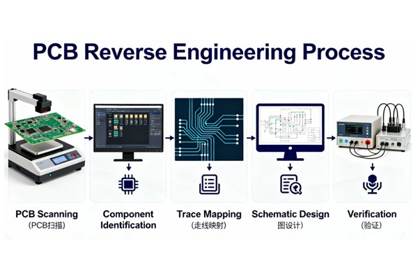
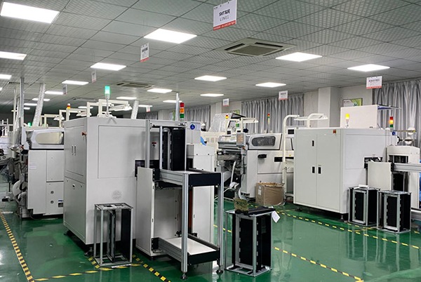
How to do PCBA fabrication
PCBA fabrication is a complex and delicate process that requires specialized knowledge and equipment. The following are the general steps for PCBA production:
1.circuit design: according to the functional requirements of electronic products, design circuit diagrams, and use professional EDA software, such as Altium Designer, etc., circuit board design.
2.printed circuit board manufacturing: the design of the circuit diagram printed production into a solid circuit board, which usually needs to be through photolithography, etching, drilling and other steps.
3.component procurement: according to the circuit design, procurement of the appropriate electronic components, including resistors, capacitors, inductors, diodes, transistors, integrated circuits and so on.
44component assembly: the procurement of components in accordance with the circuit design requirements placed on the printed circuit board, which usually need to be carried out through the mounter and other specialized equipment.
5.welding: components and printed circuit board welding, including wave soldering, reflow soldering and other methods.
6.Testing: Test the completed PCBA, including visual inspection, electrical testing, functional testing, etc., to ensure that its function is correct and free of defects.
7.Packaging:Packaging and labeling of the tested PCBA, including anti-static packaging, moisture-proof packaging, etc., to ensure its safety in the transportation and use of the process.
PCBA Application Areas
PCBA technology has been deeply integrated into various fields of modern society:
Consumer electronics: the miniaturized core of smartphones and tablets
Automotive industry: the nerve center of electrification and intelligent driving
Medical equipment: the lifeline of high-precision diagnostic instruments
Industry 4.0: the control core of intelligent manufacturing systems
Aerospace industry: the technological cornerstone of highly reliable equipment
Future Development Trends
1.Heterogeneous integration technology
2.5D/3D packaging breaks through the plane limitation
Silicon photonics integration to enhance transmission bandwidth
2.Green Manufacturing Transformation
Lead-free process popularization
Recyclable Material Application
3.Digital Twin Application
Virtual Prototyping Accelerates Development
Intelligent Predictive Maintenance
In the PCBA design and manufacturing process, the correct selection and rational use of electronic components is crucial. Designers need to select the appropriate types and specifications of electronic components based on the functional requirements of the circuit, performance requirements and cost considerations. At the same time, it is also necessary to consider the layout of components, soldering process and reliability to ensure that the quality and performance of the circuit board meets the expected requirements.
Related Posts