PCB Board Fixing Method
Major PCB mounting techniques include mechanical fastening, structural clamping, and encapsulation methods. Includes detailed technical specifications, performance comparisons, and selection guides to help engineers choose the best fastening solution based on reliability requirements, environmental conditions, and production considerations.
Table of Contents
Introduction to PCB Mounting
Printed circuit boards (PCBs) serve as the foundational framework of electronic devices, carrying various electronic components and enabling electrical connections. Proper mounting and fixation are crucial not only for ensuring stable circuit operation but also for enhancing product durability and maintenance convenience. This comprehensive guide explores all major PCB mounting methods, their advantages, limitations, and ideal applications to help you make informed decisions for your electronic designs.
Mechanical Fastening Methods
1. Screw Mounting (Most Reliable)
Technical Specifications:
- Screw hole diameter should exceed screw outer diameter by 0.1-0.2mm
- Typically requires positioning columns for accurate alignment
- Recommended torque: 0.6-1.2N·m for M2.5-M4 screws
- Material pairing: Stainless steel screws with brass threaded inserts preferred
Advantages:
- Highest reliability and vibration resistance
- Excellent load-bearing capacity (ideal for computer motherboards)
- Allows for precise pressure control through torque adjustment
Limitations:
- Higher assembly cost and longer installation time
- Requires access space for screwdrivers
- Potential for over-tightening damage
Best For: Industrial equipment, automotive electronics, and devices requiring high impact resistance
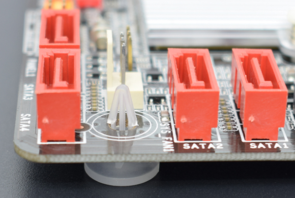
2. Snap-fit Mounting (Most Cost-Effective)
Design Parameters:
- Engagement depth ≥0.5mm
- Width ≥3mm
- Typically combined with 1-2 screws for enhanced stability
- Draft angle: 30-45° for easy assembly/disassembly
Advantages:
- Rapid assembly (reduces production time by 20-30%)
- Eliminates fasteners, reducing BOM cost
- Space-efficient design
Limitations:
- Limited vibration resistance
- Plastic fatigue over multiple cycles
- Requires precise mold tooling
Best For: Consumer electronics, IoT devices, and small appliances
Structural Clamping Solutions
3. Enclosure Clamping
Implementation Guidelines:
- Minimum 3mm clamping area on PCB edges
- Should incorporate anti-misalignment features
- Recommended for boards >150mm in length
Advantages:
- No additional fasteners needed
- Excellent for boards with dense connectors
- Simplifies the assembly process
Limitations:
- Requires robust enclosure design
- Limited suitability for high-vibration environments
- Board thickness variations affect performance
Best For: Medium-sized control boards and interface-heavy designs
4. Sheet Metal Mounting
Technical Options:
- PEM studs (press-fit threaded inserts)
- Spacer columns (brass or nylon)
- Stacking height tolerance: ±0.1mm per board
Advantages:
- Ideal for multi-board arrangements
- Provides consistent board-to-board spacing
- Allows for thermal management
Limitations:
- Increased assembly complexity
- Higher tooling costs
- Potential for galvanic corrosion
Best For: Industrial control systems and power electronics
Encapsulation and Special Processes
5. Potting and Encapsulation
Material Options:
- Epoxy resins (IP68 protection)
- Silicone gels (vibration damping)
- Polyurethane (cost-effective alternative)
Process Considerations:
- Cure time: 2-24 hours, depending onthe material
- Requires venting for outgassing
- Pot life typically 30-90 minutes
Advantages:
- Superior environmental protection
- Excellent vibration damping
- Enhanced thermal management
Limitations:
- Irreversible process
- Difficult rework/repair
- Added weight
Best For: Automotive, aerospace, and harsh environment applications
6. Insert Molding
Process Parameters:
- Injection temperature: 180-220°C
- Cycle time: 30-60 seconds
- Maximum component height: 10mm
Advantages:
- True hermetic sealing
- Eliminates secondary assembly
- Excellent part consolidation
Limitations:
- High tooling investment
- Thermal stress on components
- Limited to simple PCB designs
Best For: High-volume disposable electronics and miniaturized devices
Emerging Mounting Technologies
7. Conductive Adhesive Bonding
Technical Specifications:
- Sheet resistance: <0.01Ω/sq
- Cure temperature: 120-150°C
- Bond strength: 5-10MPa
Advantages:
- No mechanical stress on boards
- Enables flexible interconnects
- Suitable for heterogeneous integration
Limitations:
- Limited repairability
- Specialized equipment required
- Long-term reliability data is scarce
8. Optical Interconnect Integration
Performance Characteristics:
- Data rates: >25Gbps per channel
- Alignment tolerance: ±5μm
- Insertion loss: <1dB per connection
Advantages:
- EMI immune
- Ultra-high bandwidth
- Weight reduction
Limitations:
- Niche application
- High precision required
- Cost-prohibitive for most applications
Selection Methodology
Decision Matrix:
| Criteria | Screw | Snap-fit | Enclosure | Potting | Insert Mold |
|---|---|---|---|---|---|
| Reliability | ★★★★★ | ★★☆☆☆ | ★★★☆☆ | ★★★★★ | ★★★★☆ |
| Assembly Speed | ★★☆☆☆ | ★★★★★ | ★★★★☆ | ★★☆☆☆ | ★★★★★ |
| Repair Ability | ★★★★★ | ★★★★☆ | ★★★★☆ | ★☆☆☆☆ | ★☆☆☆☆ |
| Cost Efficiency | ★★☆☆☆ | ★★★★★ | ★★★★☆ | ★★★☆☆ | ★★☆☆☆ |
| Space Savings | ★★☆☆☆ | ★★★★★ | ★★★☆☆ | ★★★★☆ | ★★★★★ |
Environmental Considerations:
- Vibration >5G: Screw or potting preferred
- IP67+ requirements: Potting or insert molding
- High-temperature: Screw with high-temp plastics
- Medical sterilization: Snap-fit with USP Class VI materials
Maintenance and Serviceability
Design for Service Guidelines:
- Field-replaceable units should use screw or snap-fit
- Potting should be limited to non-serviceable modules
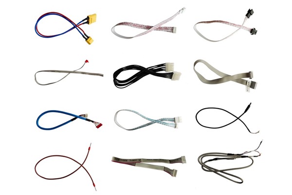
- Provide service loops for wired connections
- Mark disassembly points clearly
- Consider tool access in enclosure design
Mean Time To Repair (MTTR) Reduction:
- Standardized fastener types
- Color-coded connectors
- Guided assembly features
- QR codes linking to service manuals
Future Trends in PCB Mounting
- Smart Fasteners: IoT-enabled screws monitoring preload and corrosion
- Self-Healing Polymers: Automatic repair of snap-fit features
- Nanostructured Adhesives: High-strength conductive bonds curing at room temperature
- 4D Printed Clips: Shape-memory mounting features adapting to thermal changes
- Biodegradable Mounts: Sustainable alternatives for disposable electronics
Optimizing Your Mounting Strategy
Selecting the appropriate PCB mounting method requires careful consideration of:
- Product lifecycle requirements
- Environmental conditions
- Production volume
- Service expectations
- Cost targets
For most commercial applications, a hybrid approach combining snap-fit features with strategic screw locations offers the best balance of reliability, manufacturability and cost. Industrial applications typically demand screw mounting or potting, while consumer electronics increasingly adopt advanced insert molding techniques.

Related Posts