What is ICT?
Table of Contents
What is ICT (In-Circuit Test)?
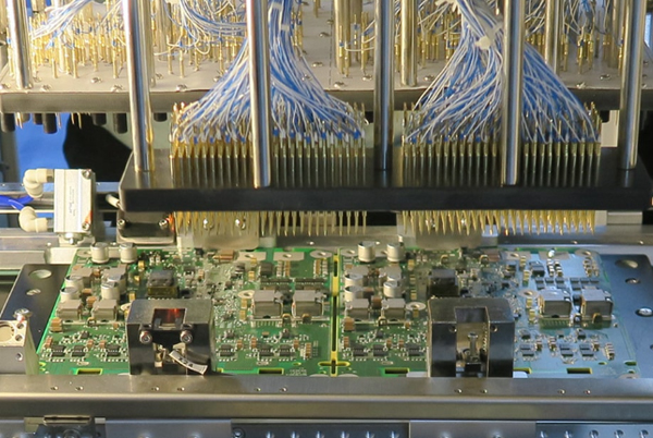
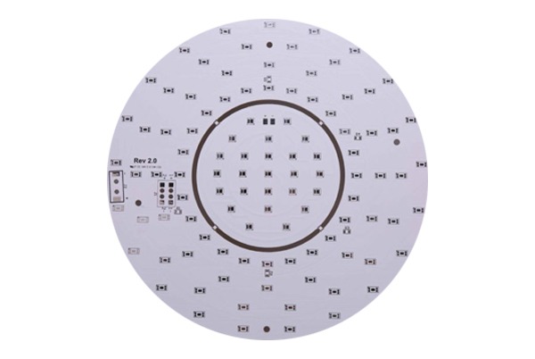
ICT (In-Circuit Test, Online Testing) is an automated testing technology used to inspect printed circuit boards (PCBA). It employs a needle bed or flying probes to contact test points, enabling rapid verification of component soldering quality, short circuits, open circuits, incorrect components, and electrical parameters. The ICT tester (In-Circuit Tester) is a critical PCBA testing device in modern electronics manufacturing, enhancing production efficiency and reducing defect rates. It is widely applied in sectors such as consumer electronics, automotive electronics, and communication equipment.
ICT Testing Functions & Working Principles
Key Features of ICT Testing
- Wide Applicability & High Accuracy
- Detects defects (opens, shorts, wrong components) with clear fault indication
- Standardized testing method, suitable for operators with basic technical skills
- Improves production efficiency and reduces costs
- Comprehensive Component Testing
- Tests PCBA for:
- Open/short circuits
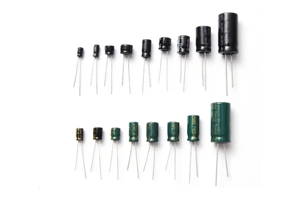
- Resistors, capacitors, diodes, transistors (FETs, BJTs)
- IC pin verification (TestJet, Connect Check, BIST)
- Missing/wrong components, soldering defects, parameter deviations
- Faults are displayed via the screen or printer for quick troubleshooting
- Advanced Functions
- TTL/OP/Relay functional testing
- IC programming (firmware burning)
How ICT Testing Works
- Guarding (Isolation) Technique
- Uses operational amplifiers to isolate connected components, ensuring accurate measurements.
- Formula: R1 = Vm/I1 (current through R2 ≈ 0).
- Resistor Testing
- Constant Current Method: Measures large resistors via Ohm’s Law (R = V/I).
- Inverting Amplifier Method: Calculates resistance (Rdut = -Vi×Rf/Vo).
- Capacitor Testing
- AC Mode: Measures reactance (Xc = 1/(2πfC)) using OPA amplification (C = -Vo/(V×ω×R)).
- DC Mode (for >10μF): Charges capacitors with constant current; calculates capacitance via charge time.
- Inductor Testing
- Measures inductive reactance (XL = 2πfL) using OPA (L = -V×R/(ω×Vo)).
- Diode/Transistor Testing
- Diodes: Forward voltage check (Si: ~0.7V, Ge: ~0.3V).
- Transistors: Pulse base input; Vce < 0.2V indicates saturation (pass).
- Open/Short Testing
- Learning Mode: Creates a “Short Pin Group Table” (resistance <20Ω = short).
- Test Mode:
- Open Test: Resistance >80Ω = open fault.
- Short Test: Resistance <5Ω between groups = short fault.
Applications and Limitations of ICT
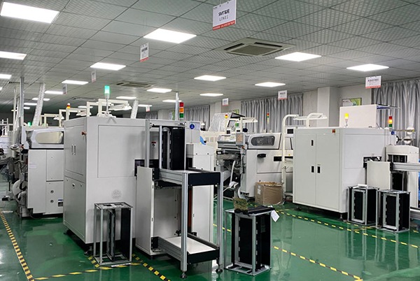
ICT (In-Circuit Test) is primarily used at the end of the SMT process, typically after reflow soldering, to quickly detect PCB assembly defects (such as shorts, opens, or wrong components) and monitor SMT production yield in real time.
Key Points:
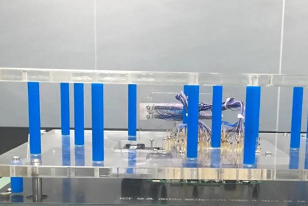
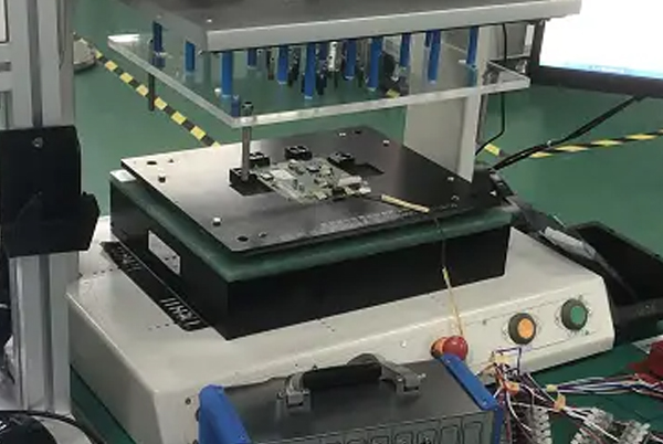
- Requires Custom Fixtures: Different products need dedicated ICT test fixtures, commonly including vacuum or pneumatic types, which use probes to contact test points.
- Testing Limitations: If PCB components are too densely packed, ICT may be impractical due to insufficient space for probe placement.
Industries: Widely used in high-precision PCBA manufacturing, such as consumer electronics, automotive electronics, and communication devices.
ICT Testing Advantages, Disadvantages
Advantages of ICT Testing
High Speed & Efficiency
- Tests L/C/R/D components without powering the PCB (e.g., 300-component PCB tested in 3–5 seconds).
- Reduces startup delays and prevents short-circuit damage.
Consistent & Reliable
- Computer-controlled precision minimizes false failures and missed defects.
- Low operator dependency—basic training suffices for operation (though programming requires engineers).
Cost-Effective Repairs
- Pinpoints faulty components/nets, speeding up debugging.
- Reduces labor costs with easy troubleshooting for technicians.
Boosts Production Yield
- Real-time feedback to SMT lines lowers defect rates.
- Improves throughput and reduces scrap inventory.
Comprehensive Quality Control
- Tests all components, including bypass circuits, enhancing end-product reliability.
Disadvantages of ICT Testing
High Initial Costs
- Equipment/fixtures (e.g., pneumatic models) can cost $10K–$ 50 K+, favoring mass production.
Design Constraints
- Requires dedicated test points (TPs), reducing PCB layout flexibility.
Contact Reliability Issues
- Surface treatments (e.g., OSP) may need solder paste for conductivity but risk oxidation-induced failures.
Maintenance Demands
- Probes and fixtures require regular replacement/cleaning for accuracy.
ICT vs. MDA vs. ATE: Key Differences
| Test Type | Capabilities | Examples |
|---|---|---|
| MDA | Basic L/C/R/D testing; no power supply (like “automated multimeter”) | TRI-518, JET-300 |
| ICT | Advanced: Self-testing, power delivery, functional checks | Agilent 3070, TRI-8100 |
| ATE | End-to-end functional testing requires a powered PCB | Custom SMT-line systems |
Top ICT Manufacturers
- Leading Brands: Agilent (Keysight), Teradyne, TRI (Taiwan), GenRad, SPEA
- Others: Hioki (Japan), ADSYS (Taiwan), WINCHY (China), AEROFLEX (USA)
(Note: Agilent 3070 and TRI-518 are most common in OEM factories.)
ICT Testing FAQ
Q1: What is ICT Testing?
A1: ICT (In-Circuit Test) is an automated technology used to detect PCBA assembly defects (shorts, opens, wrong components, etc.) by using test probes to quickly verify component electrical performance and soldering quality.
Q2: What components can ICT test?
A2: ICT can detect:
- Basic components: Resistors (R), capacitors (C), inductors (L), diodes (D)
- Circuit conditions: Opens, shorts
- IC protection diodes, etc.
Q3: Why is ICT testing necessary?
A3:
- Efficient detection: Identifies over 90% of assembly defects (e.g., soldering issues, missing parts) quickly.
- Cost reduction: Early defect detection minimizes rework time and expenses.
Q4: Is ICT just an advanced multimeter?
A4: Yes, but with key advantages:
- Guarding (isolation): Precisely measures individual components in-circuit without signal interference.
- Batch testing: Simultaneously checks multiple PCB components via a test fixture.
Q5: How does ICT differ from AOI?
A5:
| Test Type | Method | Strengths | Best For |
|---|---|---|---|
| ICT | Electrical testing | Detects functional defects (opens, parameter errors) | Electrical validation |
| AOI | Optical inspection | Identifies visual defects (misalignment, missing solder) | Appearance checks |
- Recommended workflow: AOI (visual) → ICT (electrical).
Summary
ICT (In-Circuit Test) is a critical automated testing technology for PCBA manufacturing, enabling rapid detection of electrical defects like shorts, opens, and component failures. Unlike AOI (optical inspection), ICT validates functional performance through precision electrical measurements, leveraging guarding techniques for accuracy. This FAQ covers its core capabilities, advantages over manual testing, and integration with production workflows, making it indispensable for quality control in electronics assembly.

Related Posts