Key PCB Design Strategies and Modern Manufacturing Techniques
As a PCB designer, printed circuit board design is not merely the blueprint for electronic hardware—it is the core element that determines a device’s performance, reliability, and cost. Every layout decision, every trace, and every via helps streamline the design process, resulting in more efficient, stable, and reliable products.
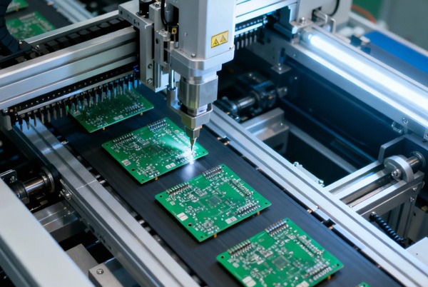
Table of Contents
Fundamental Knowledge in PCB Design
1. Stackup Structure: The Foundation of Performance
The stackup is more than just layers of copper and insulating material; it defines the electrical characteristics and mechanical strength of the board. A rational stackup design can significantly enhance signal integrity, control impedance, and reduce electromagnetic interference. For example, in high-frequency applications, selecting materials with low dielectric constants (like Rogers or Isola) can reduce signal loss, while the arrangement of ground and power planes in multi-layer boards directly impacts power integrity and thermal management.
Design Insight: It’s advisable to communicate with the manufacturer early about the stackup plan, ensuring material thickness, copper type, and dielectric constant meet practical needs, thus avoiding signal distortion due to impedance mismatch later.
2. Synchronizing Schematics and Layout
The schematic is the logical soul of the circuit, while the layout is its physical realization. Many design issues stem from inconsistencies between schematics and layouts, such as netlist errors or footprint mismatches. Modularizing complex circuits through hierarchical design and using ERC and DRC tools to check logical and physical rules can greatly reduce design iterations.
Design Insight: Develop the habit of forward/backward annotation to ensure any changes in the schematic are synchronized in real-time with the layout. Tools are helpful, but human diligence is the real guarantee of quality.
3. The Art of Component Placement
Component placement determines the ease of routing, heat dissipation efficiency, and electromagnetic compatibility. My experience is: prioritize placing high-frequency and sensitive components (like clock chips and analog devices), ensuring they are away from high-current switching devices; place decoupling capacitors as close as possible to IC power pins (within 1-3mm) to reduce loop inductance; lay copper and add thermal vias under heat-generating components to prevent local overheating.
Design Insight: Using a “zonal placement” approach to physically isolate high-speed, analog, and power areas can effectively reduce noise coupling and improve overall performance.
4. Fine Management of Routing
Routing is not just about connections; it’s part of electromagnetic design. Calculate trace width according to IPC-2152 standards to ensure current-carrying capacity; differential pairs must strictly maintain length matching and symmetrical spacing to avoid timing errors; minimize the number of vias, and use back-drilling when necessary to reduce parasitic parameters.
Design Insight: Treat high-speed traces as transmission lines, not simple wires. Using simulation tools to predict signal integrity allows potential risks to be mitigated during the layout phase.
5. Optimizing Power and Ground Planes
Power and ground planes are the “lifeblood” of the circuit. Continuous low-impedance planes provide stable current return paths, while split planes require careful handling—improper splits can force return paths to detour, increasing electromagnetic radiation. In multi-voltage systems, using star connections or ferrite beads to isolate different areas can effectively suppress noise propagation.
Design Insight: PDN impedance analysis should not be an afterthought but an essential step early in the design process. Verifying decoupling capacitor placement and plane resonance through simulation can identify power integrity issues in advance.
Advanced Design Techniques: From Theory to Practice
1. Signal Integrity in High-Speed Design
At gigahertz frequencies, traces behave as transmission lines. Controlling impedance (e.g., 50Ω single-ended or 100Ω differential), matching lengths, and using termination techniques can reduce reflections and crosstalk. For example, in PCIe routing, length deviation must be controlled within picoseconds, and the reference plane must be continuous.
Practical Tip: Use field solvers to calculate impedance and verify eye diagram quality through simulation to ensure “healthy” signal transmission on the board.
2. Thermal Management Strategies
High temperatures are the “silent killer” of electronic components. Beyond conventional thermal vias and copper pours, consider metal-core substrates (like aluminum) or high-Tg materials for high-power applications to improve thermal conductivity.
Practical Tip: Use thermal simulation tools during layout to locate hot spots and optimize component spacing and heat dissipation paths to prevent field failures.
3. Design for Manufacturability (DFM)
DFM bridges design and manufacturing. Details like minimum trace width/spacing, clearance between pads and solder mask, and annular ring size must align with the manufacturer’s capabilities. For example, avoid extreme aspect ratios to prevent drill breakage.
Practical Tip: Use the manufacturer’s DFM tools for real-time checks to identify and fix manufacturability issues before submitting the design for production.
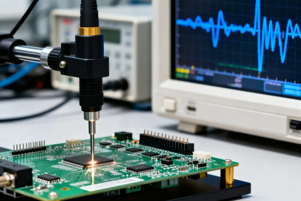
4. Electromagnetic Compatibility (EMC) Design
EMC compliance is a mandatory step for product market release. Techniques like ground stitching, shields, and filter circuits can effectively suppress electromagnetic interference. Clock signals should be kept away from board edges, and guard traces added in sensitive areas.
Practical Tip: Use near-field probes during testing to scan for radiation hot spots and optimize layout and shielding solutions accordingly.
Common Design Pitfalls and How to Avoid Them
- Poor Grounding Design: Floating grounds or ground loops can cause noise and signal distortion. Use star grounding or single-point grounding to ensure low-impedance return paths.
- Incorrect Trace Width and Spacing: Traces that are too thin can overheat; spacing that is too tight may cause short circuits. Strictly follow IPC standards and determine parameters based on current-carrying calculations.
- Neglecting Thermal Management: Inadequate heat dissipation for hot components can lead to performance degradation. Perform thermal simulations early and use thermal materials to enhance cooling.
- Insufficient DRC Checks: Neglecting design rule checks can lead to manufacturing disasters. Always run a comprehensive DRC before board submission, confirming vias, pads, and spacing meet specifications.

A Designer’s Reflection: The Value of Tools and Collaboration
Modern PCB design relies on automation tools. AI-driven routing software can optimize differential pair placement and predict signal integrity issues, but tools are ultimately aids—the designer’s experience and judgment are paramount. Simultaneously, close collaboration with manufacturers is crucial; their process feedback helps us balance performance and manufacturability.
As a designer, I firmly believe that high-quality PCBs are the crystallization of theory and practice. From stackup planning to routing optimization, from signal integrity to thermal management, every detail deserves scrutiny. Only by combining rigorous design strategies with advanced manufacturing techniques can we perfectly realize our creativity on the circuit board.


Related Posts