PCB reliability cannot be assumed based on appearance or initial electrical test results alone.
Many failures occur after prolonged thermal, mechanical, or electrical stress, even when a PCB initially passes inspection.
Reliability testing is designed to:
- Reveal latent defects
- Validate material and process choices
- Predict long-term field performance
This article explains the main PCB reliability testing methods, what they evaluate, and how manufacturers use them to improve quality.
For defect root causes, see:
PCB Manufacturing Defects and How to Prevent Them
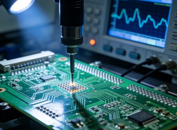
Table of Contents
What Is PCB Reliability Testing?
PCB reliability testing evaluates a board’s ability to:
- Maintain electrical integrity
- Withstand environmental stress
- Survive mechanical and thermal cycling
- Perform consistently over time
Unlike functional testing, reliability testing focuses on failure mechanisms, not short-term performance.
Thermal Reliability Testing
Thermal stress is the most common cause of PCB failure, especially in multilayer and high-density designs.
H3: Thermal Cycling Test
Purpose
- Simulates repeated heating and cooling
- Detects via fatigue and micro-cracking
Typical Conditions
- −40°C to +125°C (or higher)
- Hundreds to thousands of cycles
Failure Indicators
- Intermittent opens
- Increased resistance
- Via barrel cracks
Related process risk:
Copper Plating Process in PCB Manufacturing
Thermal Shock Test
Purpose
- Applies rapid temperature transitions
- Accelerates failure mechanisms
Difference vs Thermal Cycling
- Thermal shock = rapid change
- Thermal cycling = gradual change
Thermal shock is especially revealing for CTE mismatch issues between materials.
Mechanical Reliability Testing
Mechanical stress affects PCBs during:
- Assembly
- Transportation
- Installation
- Vibration in operation
Vibration Testing
Purpose
- Simulates operational vibration
- Evaluates solder joints and vias
Common Applications
- Automotive
- Industrial control
- Aerospace
Bend and Flex Testing
Purpose
- Evaluates board rigidity and layer adhesion
- Detects delamination and copper cracking
This test is critical for:
- Thin boards
- Large panel sizes
- High copper weight designs
Stack-up influence:
PCB Material and Layer Structure
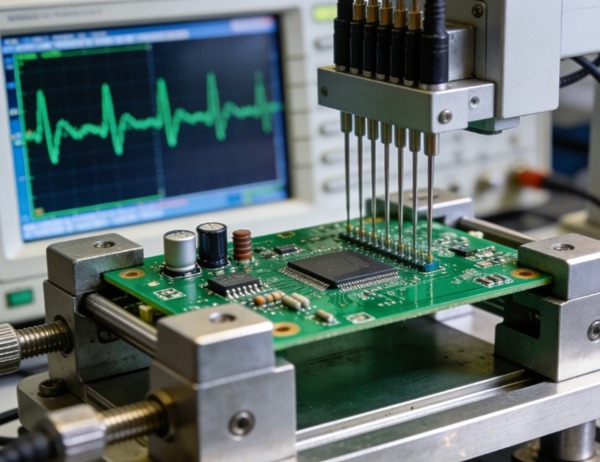
Electrical Reliability Testing
Insulation Resistance (IR) Test
Purpose
- Measures leakage between conductors
- Evaluates dielectric performance
Low insulation resistance indicates:
- Contamination
- Moisture absorption
- Material degradation
High Voltage (Hipot) Testing
Purpose
- Applies voltage beyond normal operating levels
- Detects dielectric breakdown
Hipot testing is common for:
- Power electronics
- High-voltage PCBs
CAF (Conductive Anodic Filament) Testing
Purpose
- Evaluates the risk of conductive filament growth
- Critical for fine-pitch, high-density boards
CAF failures often occur months or years after deployment.
Environmental Reliability Testing
Common Environmental Tests
- High-temperature storage
- High humidity exposure
- Temperature-humidity bias (THB)
These tests reveal:
- Moisture-related delamination
- Corrosion risks
- Long-term dielectric degradation
Defect interaction:
Common PCB Manufacturing Defects
Standards Used in PCB Reliability Testing
PCB reliability testing commonly follows standards such as:
- IPC-TM-650
- IPC-6012 / 6013
- MIL-STD-202
- IEC standards
These standards define:
- Test conditions
- Acceptance criteria
- Failure classification
Compliance improves consistency but does not replace process control.
When Should Reliability Testing Be Applied?
Reliability testing is especially important for:
- New designs
- New materials
- Process changes
- High-reliability applications
For mature, high-volume products, periodic testing helps monitor process drift.
Reliability Testing vs Cost Considerations
Reliability testing increases upfront cost but reduces:
- Field failures
- Warranty returns
- Reputational risk
Cost-quality relationship:
PCB Manufacturing Cost vs Quality Trade-offs
At TOPFAST, reliability testing is selectively applied based on design complexity, application risk, and customer requirements, rather than as a one-size-fits-all approach.
Limitations of PCB Reliability Testing
No test can fully replicate real-world conditions.
Limitations include:
- Accelerated stress assumptions
- Sample size constraints
- Incomplete failure mode coverage
Therefore, testing must be combined with robust design and manufacturing control.
Conclusion
PCB reliability testing provides insight into how a board will perform beyond initial inspection.
By applying thermal, mechanical, electrical, and environmental stress tests, manufacturers can:
- Identify latent defects
- Validate process capability
- Improve long-term reliability
This article serves as a key technical pillar within the PCB Quality & Reliability cluster.
FAQ: PCB Reliability Testing
A: No. Electrical testing verifies functionality, not long-term durability.
A: Thermal cycling is the most widely used and revealing test.
A: No. They are most critical for high-reliability or new designs.
A: No, but it significantly reduces failure risk.
A: Typically during new product introduction and after major process changes.