Inhoudsopgave
Introduction to Metal Core PCBs (MCPCBs)
The rapid advancement of solid-state lighting has pushed the boundaries of light-emitting diode (LED) technology, leading to the development of incredibly dense, high-power LED arrays. As the wattage and luminous efficacy of these diodes increase, so does the amount of waste heat they generate. Traditional FR4 printed circuit boards, with their inherently low thermal conductivity, are woefully inadequate for dissipating the localized heat fluxes produced by modern high-brightness LEDs. Enter the Metal Core Printed Circuit Board (MCPCB).
An MCPCB is a specialized circuit board that incorporates a base metal material as a heat spreader to dissipate heat away from critical components. By utilizing a thermally conductive but electrically insulating dielectric layer, MCPCBs allow heat to flow efficiently from the LED junction, through the copper circuitry, and into the metal core, which then transfers the thermal energy to a secondary heat sink. In the realm of high-power LED engineering, the choice of the base metal—predominantly aluminum or copper—is a critical design decision that dictates the thermal limits, mechanical properties, and economic viability of the entire lighting system. Meer informatie over Bookbinder Rigid-Flex-printplaten: een oplossing voor lengtebeperkingen bij multi-flex-lagen.
The Crucial Role of Thermal Management in High-Power LEDs
In LED physics, heat is the ultimate enemy of performance and longevity. Unlike incandescent bulbs that radiate heat away as infrared energy, LEDs operate via electroluminescence and conduct their waste heat backward into the printed circuit board. If this heat is not efficiently evacuated, the junction temperature of the semiconductor die will rise rapidly.
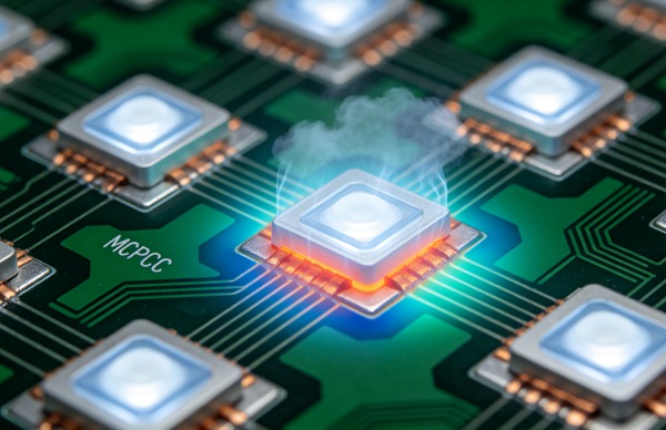
Elevated junction temperatures have three disastrous effects on high-power LEDs. First, it causes severe lumen depreciation, drastically reducing the light output for the same input power. Second, it accelerates the degradation of the phosphor coating in white LEDs, leading to chromaticity shifts (color shifting) over time, which is unacceptable in precision commercial and architectural lighting. Finally, sustained high temperatures drastically reduce the mean time between failures (MTBF), preventing the luminaire from reaching industry-standard L70 or L90 lifespan ratings (the point at which light output drops to 70% or 90% of its initial value, respectively). Efficient thermal management through a well-designed MCPCB ensures that the LED operates well within its safe thermal envelope, maximizing both efficacy and operational life.
Anatomy of a Metal Core PCB
To fully appreciate the differences between aluminum and copper bases, engineers must understand the standard tri-layer stack-up of a conventional Metal Core PCB:
Circuit Layer: The topmost layer consists of standard electrolytic or rolled copper foil (typically 1 oz to 3 oz, though heavy copper can be used for extreme currents). This layer is etched to form the electrical interconnects and mounting pads for the LEDs. Meer informatie over Biocompatibele printplaten: geavanceerde materialen voor implanteerbare medische hulpmiddelen.
Dielectric Layer: This is the most critical and technologically demanding layer of the MCPCB. It must possess high thermal conductivity while maintaining high electrical isolation (dielectric breakdown strength). Modern dielectrics are typically composed of epoxy resins highly loaded with ceramic fillers such as aluminum oxide, boron nitride, or aluminum nitride. Despite advancements, this layer often acts as the primary thermal bottleneck in the system.
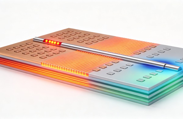
Metal Core Base Layer: The foundation of the board, usually ranging from 1.0mm to 3.2mm in thickness. This massive metal plane acts as a lateral heat spreader, taking the highly localized heat flux from the LED thermal pad and distributing it across a wider surface area before it passes into the external heatsink. The material chosen here—aluminum or copper—defines the board’s baseline thermal and mechanical characteristics.
Aluminum MCPCBs: The Industry Standard
Aluminum is the undisputed workhorse of the MCPCB industry. For the vast majority of commercial, industrial, and automotive LED applications, aluminum provides a nearly perfect balance of thermal performance, physical weight, and manufacturing cost. The most common alloys used in PCB manufacturing are 5052, 6061, and 1060, each offering slightly different balances of thermal conductivity and mechanical rigidity. Meer informatie over Ontwerp van RF-printplaten: impedantieaanpassing en beheersing van diëlektrische verliezen met materialen van Rogers.
The thermal conductivity of an aluminum base typically sits between 130 W/m·K and 237 W/m·K, depending on the specific alloy. While this is lower than copper, it is vastly superior to FR4 (which sits at a mere 0.25 W/m·K). From a manufacturing perspective, aluminum is exceptionally easy to machine. It can be routed, punched, and drilled with standard tooling without causing excessive wear on CNC bits. Furthermore, aluminum is naturally resistant to corrosion, often requiring only a simple anodization or chromate conversion coating to protect it in harsh environments.
However, aluminum has its physical limits. When dealing with extreme high-power density applications—such as UV curing LEDs, high-lumen stage lighting, or tightly packed chip-on-board (COB) arrays—the thermal spreading resistance of aluminum may not be sufficient to keep the junction temperatures within safe limits, necessitating a transition to a more thermally aggressive material.
Copper MCPCBs: For Maximum Thermal Performance
When thermal loads exceed the capabilities of aluminum, engineers turn to copper. Copper (specifically high-purity C11000 or similar alloys) boasts a thermal conductivity of approximately 385 W/m·K to 400 W/m·K—nearly double that of aluminum. This massive increase in thermal transfer allows copper MCPCBs to absorb and spread heat significantly faster, reducing the overall thermal resistance of the substrate.
The primary advantage of a copper base is its ability to handle incredibly concentrated heat fluxes. This makes it the material of choice for densely packed LED arrays and high-power single-die LEDs. Furthermore, copper’s physical properties allow for the manufacturing of Direct Thermal Path (DTP) PCBs. In a DTP board, the thermally insulating dielectric layer is selectively removed or milled away directly beneath the LED’s thermal pad. The LED is then soldered directly to a raised pedestal on the solid copper base. By completely bypassing the dielectric bottleneck, DTP copper boards offer the absolute lowest thermal resistance possible in planar board design. Meer informatie over SMT-stencilontwerp: nanocoating en stapstencils voor gemengde technologie.
Despite these immense thermal benefits, copper has notable drawbacks. It is significantly heavier than aluminum, which can be a disqualifying factor in aerospace, automotive, or portable lighting applications where mass must be minimized. Copper is also substantially more expensive, both as a raw material and in manufacturing. It is harder to machine, wearing out router bits faster, and it requires plating (such as ENIG or HASL) to prevent rapid oxidation and tarnishing of the exposed base metal.
Aluminum vs. Copper MCPCB: A Direct Technical Comparison
To facilitate a quantitative engineering decision, let us look at the direct comparative metrics between the two base materials:
- Warmtegeleidingsvermogen: Copper dominates this category (~400 W/m·K) compared to Aluminum (~200 W/m·K). Copper spreads heat faster and reduces localized hot spots under the LED die.
- Density and Weight: Aluminum (~2.7 g/cm³) is roughly one-third the weight of Copper (~8.9 g/cm³). For weight-sensitive designs, aluminum is strictly superior.
- Coefficient of Thermal Expansion (CTE): The CTE of Copper (~16.5 ppm/°C) is generally closer to that of the dielectric and the ceramic substrates of the LEDs themselves than Aluminum (~23.6 ppm/°C). This closer CTE match reduces thermo-mechanical shear stresses on the solder joints during rapid thermal cycling, improving long-term reliability.
- Machinability: Aluminum is softer and highly machinable, allowing for rapid, low-wear routing and punching. Copper requires specialized tooling feeds and speeds, increasing fabrication time and tooling costs.
- Cost: Copper is considered a premium material. Depending on market fluctuations, a copper-based MCPCB can cost anywhere from two to four times as much as an equivalent aluminum-based board.
How to Select Between Aluminum and Copper for Your LED Project (Step-by-Step Guide)
Houd u aan deze technische voorschriften.
- Calculate the System Thermal Load
Begin by determining the total power dissipation of your LED array. Review the specific LED datasheet to find the maximum operating junction temperature ($T_{j-max}$) and the thermal resistance from the junction to the solder pad ($R_{th-js}$). This will provide the baseline thermal budget you have to work with.
- Identify the Primary Thermal Bottleneck
Evaluate whether the metal base is actually the limiting factor. In many standard MCPCBs, the dielectric layer is the primary thermal bottleneck. Before jumping to an expensive copper base, calculate whether upgrading the dielectric (e.g., moving from a 1 W/m·K to a 5 W/m·K or 8 W/m·K dielectric) on an aluminum base achieves the necessary thermal resistance at a lower cost.
- Assess Space and Weight Constraints
Review the physical and mechanical limitations of your luminaire housing, chassis, or enclosure. If the product is destined for aerospace, automotive headlamps, or portable handheld lighting, the high density of copper may exceed your mass budget, making aluminum the mandatory choice regardless of thermal constraints.
- Evaluate the Project Budget
Copper MCPCBs represent a significant cost increase over aluminum. Perform a rigorous cost-benefit analysis. Determine if the enhanced thermal performance of copper—which might allow you to run fewer LEDs at higher drive currents or use a smaller external heatsink—ultimately offsets the higher PCB fabrication costs.
- Consider Direct Thermal Path (DTP) Technologies
If your thermal modeling indicates that standard dielectric layers will not suffice, investigate DTP copper boards. By soldering the LED thermal pad directly to the copper base, you eliminate the dielectric entirely under the heat source. This is often the only viable solution for ultra-high-power UV or high-density COB LEDs.
Choosing the correct MCPCB substrate requires a systematic approach to thermal and mechanical engineering. Follow this structured methodology to make the right material selection.
Veelgestelde vragen (FAQ)
Standard FR4 has an extremely low thermal conductivity (typically 0.25 to 0.3 W/m·K). While it can be utilized for low-power indicator LEDs, or combined with a dense array of thermal vias for mid-power applications, it is generally inadequate for high-power LED arrays. FR4 traps heat, leading to rapid thermal runaway, color shifting, and catastrophic LED failure.
A DTP Copper PCB is an advanced fabrication technique where the dielectric layer is removed beneath the LED’s thermal pad footprint. The LED is soldered directly to a pedestal on the solid copper base. This configuration completely bypasses the thermal resistance of the dielectric layer, maximizing heat transfer and allowing for extreme power densities.
Yes. The thickness of the metal core influences its lateral heat spreading capability and its structural rigidity. A thicker base (such as 2.0mm or 3.2mm) spreads heat more effectively across the x-y plane before transferring it to the external heatsink, which reduces hot spots. However, thicker bases also add mass, manufacturing time, and material costs.
The dielectric layer is crucial because it must simultaneously provide high electrical isolation and high thermal conductivity—two inherently contradictory properties. Since the base metal (whether aluminum or copper) is highly conductive, the dielectric typically represents the highest thermal resistance in the entire board stack-up. Selecting a high-performance dielectric (e.g., 5-8 W/m·K) is often more critical to the board’s success than the choice between aluminum and copper.