PCB Drilling Techniques
Table of Contents
1. Overview of PCB Drilling Technology
Drilling is the most expensive and time-consuming process in PCB manufacturing, where even minor errors can result in the complete scrapping of the board. As the foundation for through-holes and interlayer connections, drilling quality directly determines circuit board reliability and performance.
Comparison of Two Main Drilling Technologies
| Technology Type | Precision Range | Application Scenarios | Advantages/Disadvantages | Cost Analysis |
|---|---|---|---|---|
| Mechanical Drilling | ≥6 mil (0.006″) | Conventional PCB, FR4 materials | Low cost, simple operation, but drill bits wear easily | Low equipment investment but frequent bit replacement |
| Laser Drilling | ≥2 mil (0.002″) | HDI boards, high-density materials | High precision, non-contact, but high equipment cost | High initial investment but low long-term maintenance |
Technical Details Analysis
Mechanical Drilling Limitations
- Drill bit life: ~800 hits for FR4 materials, only 200 for high-density materials
- Aperture limitation: Minimum 6 mil, difficult to meet high-density requirements
- Risk warning: Bit wear causes hole position deviation, leading to board scrapping
Laser Drilling Advantages
- Non-contact processing: Avoids tool wear and material stress
- Depth control: Precise control of blind and buried via depth
- Application scope: Optimal choice for microvias and high aspect ratio holes
2. PCB Drilling Process Flow
Standard Drilling Process
- Laminate Preparation: Load laminated boards onto the drilling machine
- Protective Layer Addition:
- Exit material panels: Reduce burr formation
- Aluminum foil covering: Dissipates heat, prevents entry burrs
- Drilling Execution: CNC equipment drills according to preset coordinates
- Post-Processing:
- Deburring treatment
- Cleaning treatment
- Desmearing process
Drill Bit Geometric Parameters
- Point Angle: Standard 130°
- Helix Angle: 30°-35°
- Bit Materials: High-speed steel (HSS) or tungsten carbide (WC)
3. Key Parameter Control in PCB Drilling
1. Aspect Ratio
Definition: Indicator of effective through-hole plating capability
Calculation Formula: AR = Board thickness / Drill diameter
Industry Standards:
- Through-hole aspect ratio: 10:1
- Microvia aspect ratio: 0.75:1
- Minimum drilling for 62mil board thickness: 6mils
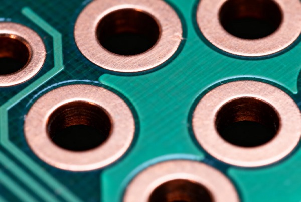
2. Drill-to-Copper Clearance
Importance: Planar clearance between drill edge and copper features
Typical Value: Approximately 8 mil
Calculation Formula: Minimum clearance = Annular ring width + Solder mask dam clearance
4. PCB Drilling Classification and Specifications
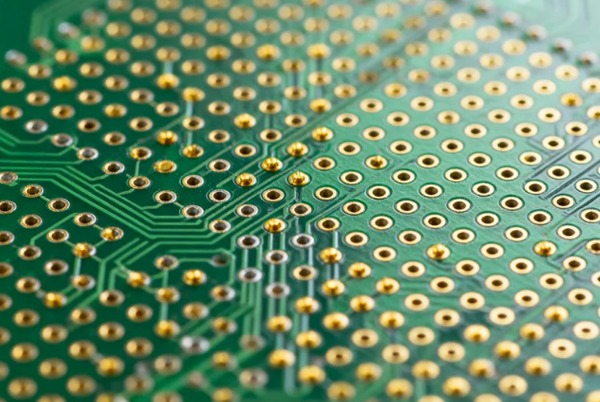
Plated Through Hole (PTH) Specifications
- Finished hole size (minimum): 0.006″
- Annular ring size (minimum): 0.004″
- Edge-to-edge clearance (minimum): 0.009″
Non-Plated Through Hole (NPTH) Specifications
- Finished hole size (minimum): 0.006″
- Edge-to-edge clearance (minimum): 0.005″
5. Common Drilling Issues and Solutions
Drilling Quality Issue Analysis
| Issue Type | Causes | Consequences | Solutions |
|---|---|---|---|
| Hole Position Deviation | Bit wear, insufficient equipment precision | Annular ring tangency or fracture | Use optical positioning systems |
| Rough Hole Walls | Improper parameters, poor chip removal | Uneven plating, pores | Optimize speed and feed rate |
| Resin Smearing | Excessive drilling temperature | Reduced conductivity | Chemical desmearing process |
| Burr Issues | Improper exit materials | Circuit short circuit risk | Mechanical deburring treatment |
| Nail Heading | Inner layer copper foil bending | Uneven plating | Adjust drill bit parameters |
| Delamination | Excessive drilling stress | Layer separation | Adopt laser drilling technology |
Professional Solutions
- Desmearing Process
- Chemical removal of melted resin
- Enhance through-hole conductivity
- Deburring Process
- Mechanical removal of copper protrusions
- Clear internal hole debris
- Delamination Prevention
- Laser drilling technology
- Optimize drilling parameters
6. Practical PCB Drilling Techniques
1. Pilot Hole Technology
- Purpose: Prevent bit “walking”
- Methods: Pre-drilling with small bits or drilling machines
- Precautions: A 0.2mm bit can pull 4 hole heads at once
2. Drill Bit Selection Guide
- Wire gauge bits: 0.8-1.0mm diameter wires
- Small bits: 0.7-2.0mm aperture
- Medium bits: 2.0-10.0mm aperture
- Large bits: ≥5.0mm aperture
3. Parameter Setting Essentials
- Speed Control:
- Mechanical drilling: 10,000-30,000 RPM
- Laser drilling: Adjust power based on material
- Feed Rate:
- FR4 boards: 50-200mm/minute
- Ceramic substrates: Appropriately reduce speed
4. Equipment Usage Recommendations
- Drilling Machine Advantages: 4x higher precision
- Operation Essentials:
- Ensure bit angle matching
- Control applied pressure
- Wear safety goggles
5. Post-Processing Techniques
- Cleaning Requirements: Use brushes and solvents to remove metal chips
- Solder Coating: Ensure proper solder adhesion
- Quality Inspection: Confirm no debris residue
7. DFM Drilling Verification Techniques
Design Optimization Suggestions
- Aspect Ratio Control: Minimize to reduce bit wear
- Bit Size Unification: Reduce different bit sizes, shorten drilling time
- Clear Drill Type Definition: Distinguish between PTH and NPTH
- File Verification: Cross-check drill files with factory print dimensions
- Small Hole Treatment: Process enclosed holes <0.006 inches
Tolerance Control Standards
- PTH Tolerance: ±0.002 inches
- NPTH Tolerance: ±0.001 inches
- Special Requirements: High-precision SMT positioning hole tolerance up to ±0.025mm
Process Optimization Measures
- Features Outside Contour: Reduce via size to meet the minimum aspect ratio
- Missing Hole Treatment: Clearly mark NPTH drill positions in manufacturing drawings
- Solder Addition: Timely solder coating after drilling
8. PCB Drilling Positioning Precision Optimization
Precision Influencing Factors
- Equipment Factors: Spindle precision, equipment stability
- Process Parameters: Speed, feed rate, cooling methods
- Material Factors: Board material, stack height
- Environmental Factors: Temperature, humidity, worktable flatness
Precision Enhancement Technologies
- Equipment Optimization
- High-precision CNC drilling machines (positioning accuracy ±0.005mm)
- Automatic tool setting systems
- Online compensation systems
- Positioning Technologies
- Optical positioning systems (micron-level alignment)
- Mechanical positioning pins
- Vacuum adsorption devices
- Advanced Technology Applications
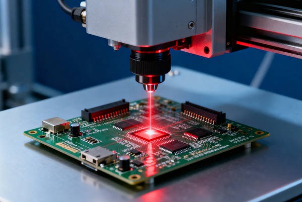
- Laser drilling technology
- CCD visual positioning systems (accuracy ±0.01mm)
- AI intelligent drilling equipment
Best Practice Recommendations
- Equipment Maintenance: Regular calibration, replace worn components
- Material Handling: Ensure surface flatness, control temperature, and humidity
- Process Control: Establish strict standards, implement first-article inspection
Summary
PCB drilling is a critical process in circuit board manufacturing, requiring comprehensive consideration of equipment capabilities, material characteristics, process parameters, and design requirements. By optimizing drilling technology, strictly controlling process parameters, and promptly addressing common issues, drilling quality and production efficiency can be significantly improved. In practical applications, it is recommended to select the most suitable drilling solution based on specific product characteristics and production conditions, and establish a complete quality monitoring system to ensure circuit board reliability and yield rate.


Related Posts