Conductive Anodic Filament (CAF) failure is one of the most challenging PCB reliability issues because it is latent, progressive, and often invisible during standard inspection.
Unlike immediate electrical defects, CAF develops slowly under specific environmental and electrical conditions, making it a critical concern for high-reliability applications.
This article explains:
- What CAF is
- How it forms
- Why is it difficult to detect
- How PCB manufacturers reduce CAF risk
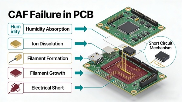
Table of Contents
What Is CAF (Conductive Anodic Filament)?
CAF is the growth of a metallic conductive path between adjacent copper features inside a PCB.
It typically forms:
- Along glass fiber interfaces
- Between closely spaced conductors
- Under electrical bias and moisture exposure
Once formed, CAF can create shorts or leakage paths.
Why CAF Is a Serious Reliability Risk
CAF failures are dangerous because they:
- Appears long after manufacturing
- Cause intermittent or sudden electrical shorts
- Are difficult to reproduce in lab conditions
Many field failures traced back to CAF passing all initial electrical tests.
Related overview:
Common PCB Failures Explained
Conditions Required for CAF Formation
CAF does not occur randomly. Several conditions must be present simultaneously.
Moisture Presence
Moisture enables ionic transport inside the PCB.
Sources include:
- High-humidity environments
- Inadequate material drying
- Poor PCB storage conditions
Electrical Bias
CAF growth requires a voltage potential between conductors.
Higher risk scenarios:
- High-voltage designs
- Constant DC bias
- Narrow conductor spacing
Susceptible Material Structure
CAF often propagates:
- Along glass fiber-resin interfaces
- Through resin-starved regions
- Near drilled holes or vias
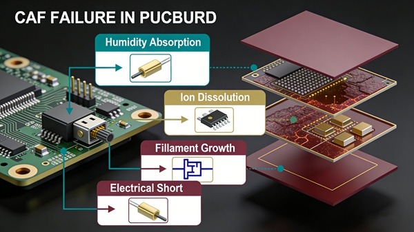
CAF Growth Mechanism
The CAF formation process typically follows these steps:
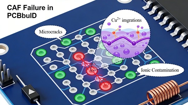
- Moisture absorption into the dielectric
- Metal ion dissolution at the anode
- Ionic migration along fiber paths
- Filament growth toward the cathode
- Electrical short or leakage formation
This process accelerates under temperature and humidity stress.
Design Factors That Increase CAF Risk
Design decisions strongly influence CAF susceptibility.
High-Risk Design Practices
- Minimal conductor spacing
- Dense via structures
- Glass fiber exposure in drilling
- High aspect ratio vias
Design reliability link:
PCB Quality & Reliability Design Guidelines
Manufacturing Factors Contributing to CAF
H3: Drilling Damage
Mechanical drilling can expose glass fibers, creating preferential CAF paths.
Process comparison:
PCB Drilling vs Laser Drilling
Inadequate Resin Fill
Poor resin distribution leaves voids that trap moisture.
Material Selection
Not all laminate systems have equal CAF resistance.
High CAF-resistant materials typically feature:
- Improved resin chemistry
- Better fiber-resin adhesion
- Reduced ionic contamination
How CAF Is Detected
CAF is difficult to detect with standard inspection.
Detection Methods Include
- Highly Accelerated Stress Testing (HAST)
- Insulation Resistance (IR) testing
- Cross-section analysis after failure
Testing overview:
PCB Reliability Testing Explained
Preventing CAF in PCB Manufacturing
Material Qualification
- CAF-resistant laminate selection
- Material supplier validation
Design Rule Optimization
- Increased spacing for high-voltage nets
- Controlled via placement
Process Control Improvements
- Optimized drilling parameters
- Improved desmear and resin flow
- Clean manufacturing environment
Manufacturers like TOPFAST incorporate CAF risk assessment during both material selection and process planning.
Relationship Between CAF and Other Failure Modes
CAF often coexists with:
- Delamination
- Via cracking
- Insulation breakdown
Related topic:
PCB Delamination Causes and Prevention
Conclusion
CAF failure is a time-dependent reliability issue driven by environmental conditions, electrical bias, and material structure.
Although difficult to eliminate, CAF risk can be significantly reduced through:
- Proper design spacing
- CAF-resistant materials
- Controlled manufacturing processes
Understanding CAF is essential for designing and manufacturing reliable PCBs for demanding applications.
CAF Failure in PCB FAQ
A: Usually not. CAF develops over time.
A: Yes, electrical bias accelerates CAF growth.
A: It helps but does not fully eliminate risk.
A: No, CAF resistance varies significantly by material system.
A: No. Once formed, CAF cannot be repaired.