Table of Contents
What are SMD Electronic Components?
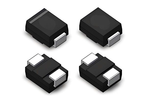
SMD components are designed to be mounted directly onto the surface of a printed circuit board. Unlike traditional through-hole technology (THT), SMDs do not require wire leads to pass through the board, which significantly reduces the parasitic inductance and allows for higher component density—a cornerstone of modern PCB design.
Common Types of SMD Components
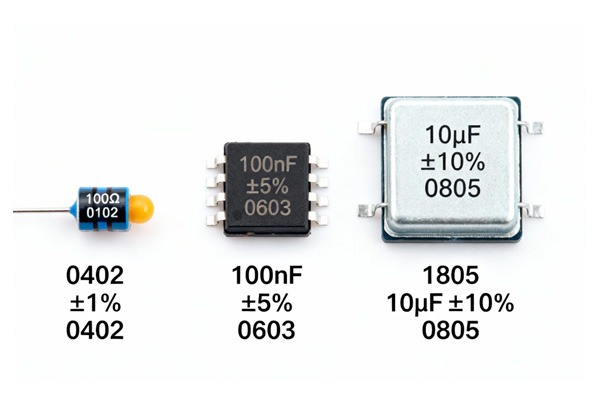
- Passive Components (Resistors & Capacitors): These are the most common SMDs, often categorised by their 4-digit size codes (e.g., 0603, 0805). If you are unsure of a component’s health during prototyping, you can follow our guide on how to test capacitors.
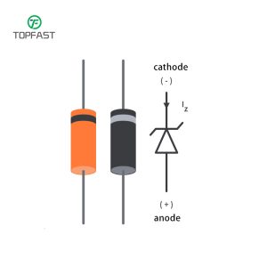
- Transistors & Diodes: Typically found in SOT (Small Outline Transistor) packages like SOT-23 or SOT-223.
- Integrated Circuits (ICs): Range from simple SOIC (Small Outline IC) to complex BGA (Ball Grid Array). For high-pin-count BGAs, an HDI PCB manufacturing process is often required to route the dense interconnections effectively.
SMD Package Size Chart (Imperial vs. Metric)
Selecting the right footprint is critical for PCB assembly. Using the wrong code can lead to “tombstoning” or soldering failures.
- 0402 (1005 Metric): Common in smartphones and wearables.
- 0603 (1608 Metric): The standard choice for most consumer electronics.
- 1206 (3216 Metric): Preferred for power resistors and larger capacitors due to better heat dissipation.
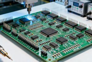
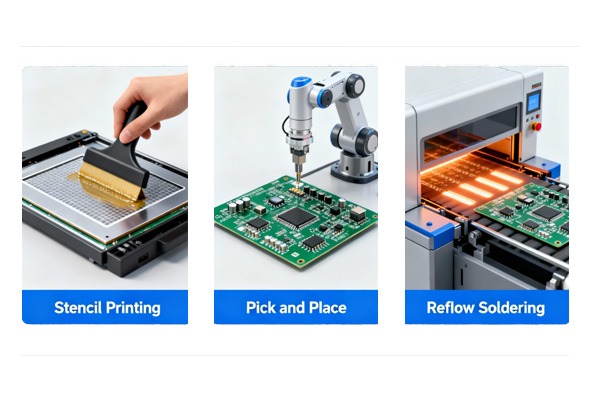
Manufacturing Considerations: SMT vs. SMD
While SMD refers to the physical part, SMT (Surface Mount Technology) is the process of placing and soldering them. To ensure high yield, designers must follow strict PCB design principles, such as proper pad sizing and thermal relief.
How to Identify and Select SMD Components for Your Project
- Step 1: Determine the Power Requirements
Choose a package size that can handle the current and thermal load. Larger packages (like 1210 or 2512) are better for power dissipation.
- Step 2: Match the Footprint to Factory Capabilities
Ensure your chosen component pitch (e.g., $0.5\text{mm}$ BGA) is within your manufacturer’s PCB manufacturing capabilities.
- Step 3: Consider Moisture Sensitivity (MSL)
For ICs, check the MSL rating to ensure they are baked or stored correctly before PCB assembly to prevent “popcorn” during reflow.
- Step 4: Optimize for Signal Integrity
Place critical SMDs (like decoupling capacitors) as close to the IC pins as possible, a key PCB design optimization strategy.
- Step 5: Verify Markings and Values
Use a digital multimeter or LCR meter to verify passive component values before starting a production run.
Frequently Asked Questions about SMD Components
A: SMD (Surface Mount Device) is the component itself, whereas SMT (Surface Mount Technology) is the assembly method used to mount SMDs onto a PCB.
A: Yes, in high-vibration environments, SMDs often perform better due to their lower mass. They also offer superior electrical performance at high frequencies.
A: Most 3-digit codes use the first two numbers as significant figures and the third as a multiplier (e.g., 103 = 10kΩ).
A: Due to their small size (like 0201), manufacturers often omit markings. Always keep them in labeled packaging or use the methods in our capacitor testing guide to verify.
A: While 0603 and larger packages can be hand-soldered with a fine-tip iron, BGA and QFN packages require professional PCB assembly services using reflow ovens.
Conclusion
Selecting the right SMD electronic components is a balance of performance, space, and manufacturability. By mastering these package standards and design rules, you ensure a smoother transition from prototype to mass production.
Need professional help with your next project? Get a Quote from Topfast today for high-quality PCB manufacturing and assembly.