When evaluating PCB materials, two parameters appear in almost every laminate datasheet: dielectric constant (Dk) and dissipation factor (Df). These values influence signal propagation, impedance control, insertion loss, and overall circuit performance.
For low-speed electronics, minor variations in Dk and Df may have little impact. However, in modern communication systems, high-speed digital products, RF circuits, and data center equipment, material properties become increasingly important.
Understanding what Dk and Df represent helps engineers select suitable materials and avoid signal integrity issues later in the design process.
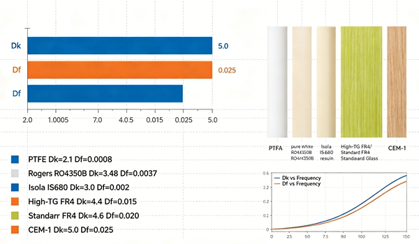
Table of Contents
What Is Dielectric Constant (Dk)?
Dielectric constant, often abbreviated as Dk, describes how an insulating material stores electrical energy.
In PCB design, Dk determines how quickly signals travel through the dielectric material.
A lower Dk generally results in:
- Faster signal propagation
- Reduced signal delay
- Lower parasitic capacitance
A higher Dk typically leads to:
- Slower signal speed
- Increased capacitance
- More compact RF structures
Every laminate material has its own dielectric constant range.
Typical values include:
| Material | Typical Dk |
|---|---|
| FR4 | 4.2 – 4.8 |
| High TG FR4 | 4.1 – 4.7 |
| Rogers 4350B | 3.48 |
| PTFE Materials | 2.1 – 2.6 |
| Megtron 6 | 3.3 – 3.5 |
As discussed in FR4 PCB Material Explained, standard FR4 remains suitable for most general-purpose electronics despite having a higher Dk than many high-frequency materials.
What Is Dissipation Factor (Df)?
The dissipation factor measures how much electrical energy is lost as heat when signals pass through a dielectric material.
It is sometimes referred to as:
- Loss tangent
- Tan δ
- Dielectric loss
Lower Df values indicate lower signal loss.
Higher Df values result in:
- Greater insertion loss
- Reduced signal quality
- Shorter transmission distances
Typical Df values include:
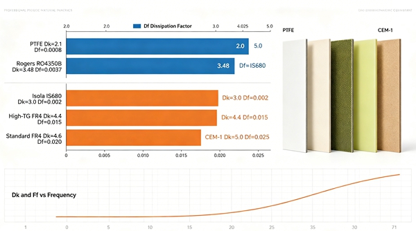
| Material | Typical Df |
| FR4 | 0.015 – 0.025 |
| High TG FR4 | 0.012 – 0.020 |
| Rogers 4350B | 0.0037 |
| PTFE Materials | 0.0009 – 0.002 |
| Megtron 6 | 0.002 |
As data rates increase, Df often becomes more important than Dk.
Why Dk Matters in PCB Design
Impedance Control
Controlled impedance structures rely heavily on dielectric constant values.
Changes in Dk directly affect:
- Trace width calculations
- Differential pair design
- Transmission line behavior
Even small Dk variations can alter target impedance.
For this reason, stackup development should always consider the actual material data supplied by the laminate manufacturer.
The relationship between dielectric properties and layer spacing is also discussed in PCB Core and Prepreg Materials.
Signal Propagation Delay
Signal velocity depends on the dielectric constant.
Lower Dk materials allow signals to travel faster through the PCB.
This becomes increasingly important in:
- High-speed networking
- AI servers
- Data center equipment
- Backplane systems
RF Circuit Performance
RF engineers often select materials partly based on Dk stability across frequency ranges.
Stable dielectric behavior improves:
- Antenna performance
- Filter design
- Phase consistency
- RF repeatability
Why Df Matters in High-Speed Design
At lower frequencies, dielectric loss is often negligible.
As frequency increases, however, Df becomes a major design consideration.
Signal Loss
A high Df value causes greater attenuation over long transmission paths.
This can create problems in:
- 25G networking
- 56G PAM4 systems
- 112G backplanes
- High-speed storage devices
Eye Diagram Performance
Lower-loss materials help maintain cleaner signal waveforms.
Benefits include:
- Reduced jitter
- Better eye opening
- Improved signal integrity
Longer Routing Distances
Low-loss materials allow designers to route high-speed signals over greater distances without requiring excessive equalization.
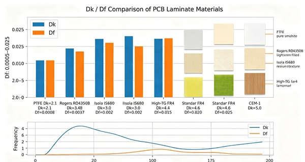
Dk and Df are frequency-dependent
One common mistake is assuming that Dk and Df are fixed values.
In reality, both properties vary with:
- Frequency
- Temperature
- Resin composition
- Test methodology
For example, a material may have:
- Dk measured at 1 GHz
- Dk measured at 10 GHz
- Dk measured using different test methods
Engineers should always verify the measurement conditions listed in the material datasheet.
Typical Material Categories
Standard FR4
Suitable for:
- Consumer electronics
- Industrial control products
- General-purpose PCBs
Advantages:
- Cost-effective
- Widely available
- Mature manufacturing process
High TG FR4
Often selected for:
- Automotive electronics
- Power systems
- Server motherboards
The primary benefit is improved thermal reliability rather than dramatically lower dielectric loss.
More details can be found in High TG FR4 PCB.
Low-Loss Materials
Designed for:
- Networking equipment
- Data center hardware
- AI computing platforms
These materials balance cost and signal performance.
RF and Microwave Materials
Examples include:
- Rogers laminates
- PTFE-based materials
- Taconic materials
These systems offer very low dielectric loss and excellent high-frequency stability.
Material Selection Considerations
When selecting PCB materials, Dk and Df should not be evaluated independently.
Other factors include:
- Operating frequency
- Thermal requirements
- Manufacturing capability
- Cost targets
- Reliability expectations
As explained in PCB Laminate Materials Explained, material selection is always a balance between electrical performance and practical manufacturing considerations.
The best material is not necessarily the one with the lowest Df value. It is the one that meets project requirements while maintaining reasonable cost and production reliability.
Common Engineering Misconceptions
Lower Dk Is Always Better
Not necessarily.
Many designs operate perfectly with FR4 materials.
Lower Dk materials are beneficial only when electrical requirements justify the additional cost.
Df Only Matters in RF Design
Modern high-speed digital systems often face the same signal loss challenges as RF circuits.
Df is now a critical consideration for many digital applications.
All FR4 Materials Have the Same Dk and Df
Different manufacturers and resin systems can produce significantly different dielectric properties.
Always review the actual material datasheet rather than relying on generic values.
FAQ
A: Dk is the dielectric constant of the material. It affects signal speed, impedance, and capacitance.
A: Df is the dissipation factor, which measures dielectric loss and indicates how much signal energy is converted into heat.
A: Both are important, but Df often becomes the dominant factor in high-speed and high-frequency applications because it directly affects signal loss.
A: Compared with specialized RF materials, FR4 has a relatively high Df, which can limit performance at very high frequencies.
A: RF materials are engineered to minimize dielectric loss, helping preserve signal quality across high-frequency transmission paths.