Table of Contents
Introduction
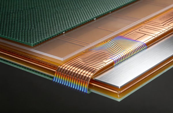
Flexible printed circuit boards (FPCs) have revolutionized modern electronics by offering unparalleled versatility, dynamic bending capabilities, weight reduction, and spatial efficiency. From ultra-compact medical implants and aerospace avionics to consumer wearables and high-density computing arrays, flex circuits allow engineers to route complex signals through highly constrained three-dimensional spaces. However, the inherent flexibility of these circuits presents unique mechanical challenges, particularly when interfacing with rigid components, interconnects, connectors, or physical mounting hardware.
To bridge the critical gap between absolute flexibility and localized rigidity, engineers employ flex PCB stiffeners. Stiffeners are not electrically conductive components of the circuit itself; rather, they are mechanical support structures applied to specific, targeted regions of the flex board. They provide essential structural integrity, prevent catastrophic mechanical stress concentrations at component solder joints, and ensure proper mating dimensions for mechanical connectors. Selecting the appropriate stiffener material is a fundamental design decision that directly impacts the overall reliability, manufacturability, and cost of the final flex PCB assembly. This comprehensive technical guide explores the three most prominent stiffener materials—FR4, Polyimide (PI), and Stainless Steel—detailing their material properties, engineering trade-offs, and optimal application scenarios.
The Critical Role of Stiffeners in Flex PCB Design
Before delving into specific material properties, it is essential to understand the multifaceted mechanical and structural roles stiffeners play in flex circuit engineering. A flexible circuit without strategically placed stiffening is highly susceptible to mechanical failure during pick-and-place assembly, manual installation, or end-use operation. Learn more about RF PCB Design: Impedance Matching and Dielectric Loss Control with Rogers Materials.
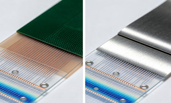
The primary engineering functions of flex PCB stiffeners include: Learn more about Metal Core PCBs (MCPCB): Aluminum vs. Copper Base for High-Power LEDs.
- Component Support and Solder Joint Protection: Surface-mounted devices (SMDs), particularly high-pin-count integrated circuits (ICs), Ball Grid Arrays (BGAs), and heavy passive components, require a completely rigid foundation. Stiffeners prevent the thin polyimide flex substrate from bending underneath these components. Even microscopic flexing under a rigid component can induce fatal shear stresses and cracking in the solder joints, leading to intermittent failures or complete open circuits.
- Connector Interfacing and Z-Axis Tolerances: Zero Insertion Force (ZIF) connectors and Low Insertion Force (LIF) connectors require a highly precise and consistent board thickness to ensure reliable electrical contact and mechanical retention. Stiffeners are utilized to locally build up the flex board tail to the exact required mating thickness (commonly 0.2mm or 0.3mm) dictated by the connector manufacturer.
- Strain Relief and Bend Radius Control: At the transition zones where a dynamic flex circuit exits a rigid section, a stiffener acts to distribute mechanical stress over a wider area. This prevents localized tearing, delamination, or copper trace fracture (often referred to as the “stress riser” effect). Furthermore, thin stiffeners can force the circuit to bend at a specific location with a controlled minimum bend radius.
- Thermal Management: High-power components, such as power management ICs, motor drivers, or high-brightness LEDs, generate localized heat. A thin polyimide substrate cannot efficiently dissipate this thermal load laterally. Thermally conductive stiffeners act as local heat spreaders or heat sinks, moving thermal energy away from critical junctions.
- Mounting, Handling, and Planarity: Stiffeners provide rigid, planar handling points for automated SMT assembly equipment, vacuum pick-up nozzles, and secure mounting interfaces for final product integration, often utilizing features like drilled holes, alignment slots, or press-fit hardware.
FR4 Stiffeners: The Industry Standard for Cost-Effective Rigidity
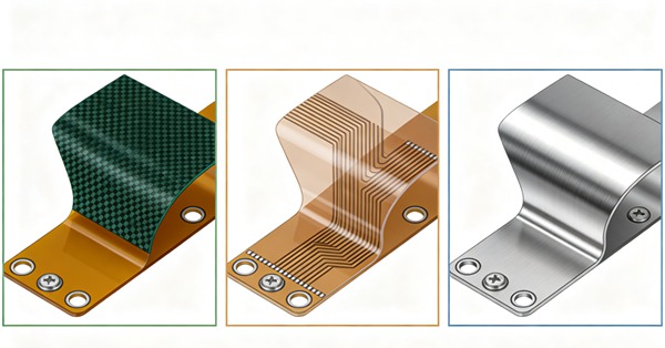
FR4, a composite material composed of woven fiberglass cloth impregnated with a flame-retardant epoxy resin binder, is the absolute standard in the rigid printed circuit board industry. Its extensive use as a stiffener in flex PCBs leverages its proven track record, vast availability, and exceptional mechanical characteristics.
Material Characteristics and Advantages:
FR4 offers exceptional mechanical rigidity, high tensile strength, and excellent dimensional stability at a highly cost-effective price point. It provides a stiff, unyielding support platform that effectively transforms the localized area of the flex circuit into a rigid board. This makes it the premier choice for supporting large component arrays, dense BGAs, or heavy through-hole connectors. Furthermore, FR4 is incredibly easy to machine. It can be easily routed, milled, and drilled, allowing for complex stiffener geometries, internal cutouts, and the inclusion of precision mounting holes.
Engineering Considerations and Disadvantages:
The primary limitation of FR4 is its inherent bulk. Standard FR4 stiffeners range from 0.2mm to 1.6mm or more in thickness, which can be prohibitive in ultra-compact, high-density designs where vertical Z-axis space is strictly limited. Additionally, the coefficient of thermal expansion (CTE) of FR4 differs significantly from that of the polyimide flex substrate. In harsh environments characterized by extreme thermal cycling, this CTE mismatch can induce shear stress at the adhesive interface, potentially leading to localized delamination if not mitigated with a robust thermosetting adhesive system.
Ideal Applications for FR4 Stiffeners:
* Structural backing for dense SMD placements, micro-BGAs, and heavy passive components.
* Edge connectors that require insertion into standard rigid receptacles.
* Regions requiring mechanical mounting holes, threaded inserts, or mechanical fastening to a chassis.
* General-purpose stiffening applications where material cost is a primary constraint and Z-axis height is reasonably flexible.
Polyimide (PI) Stiffeners: Precision Thickness and Conformity
Polyimide (PI), the exact same high-performance engineering polymer typically used for the core dielectric and coverlay of the flex PCB itself, is frequently utilized as a stiffener material. Kapton® (by DuPont) is the most recognizable brand of polyimide film used in these precise applications.
Material Characteristics and Advantages:
Polyimide stiffeners are highly prized for their minimal thickness, ultra-low profile, and exceptional manufacturing tolerance control. Unlike FR4, which is typically employed to provide heavy-duty absolute rigidity, PI stiffeners are primarily used to adjust the localized thickness of the flex circuit with pinpoint accuracy. A major engineering advantage is that since the stiffener material is identical to the core flex substrate, the thermal expansion rates (CTE) are perfectly matched. This virtually eliminates the risk of thermal-induced stress and delamination during aggressive reflow soldering profiles or prolonged harsh environmental operation. Polyimide is also inherently resistant to a wide array of chemicals, solvents, and extreme high temperatures.
Engineering Considerations and Disadvantages:
While Polyimide excels at adding localized thickness, it does not provide the absolute mechanical rigidity offered by FR4 or metals. PI is still fundamentally a flexible polymer film, albeit a thicker one when stacked and bonded. Therefore, it is generally unsuitable for supporting heavy components or providing structural rigidity for large rigid ICs. Furthermore, building up very thick layers using multiple plies of polyimide can become cost-prohibitive compared to simply using a single layer of FR4.
Ideal Applications for Polyimide Stiffeners:
* ZIF/LIF Connector Interfaces: PI is the undisputed industry standard for building up the flex tail to the exact, critical thickness required for secure, reliable insertion into Zero Insertion Force connectors.
* Bend Radius and Crease Control: Adding a strategically placed thin PI stiffener can dictate precisely where the board bends and force a larger bend radius to protect internal copper traces from work-hardening and fracture.
* High-Temperature and Aerospace Environments: Applications where the ambient operating temperature exceeds the glass transition temperature (Tg) limits of standard FR4 epoxy resins.
Stainless Steel Stiffeners: Maximum Rigidity and Thermal Performance
When neither FR4 nor Polyimide can satisfy the extreme mechanical, spatial, or thermal requirements of a design, engineers turn to metals, with Stainless Steel (typically 300-series grades like 304 or 316) being the most prominent and high-performance choice.
Material Characteristics and Advantages:
Stainless steel stiffeners provide an unmatched rigidity-to-thickness ratio. A micro-thin sheet of stainless steel (e.g., 0.1mm to 0.15mm) can offer the same or significantly greater mechanical support as a vastly thicker piece of FR4. This makes stainless steel invaluable in highly constrained spatial envelopes like modern smartphones, advanced wearables, and implantable medical devices.
Beyond absolute structural mechanics, stainless steel boasts excellent thermal conductivity. When bonded with a thermally conductive adhesive, it serves as a highly effective localized heat spreader for high-power components. Furthermore, depending on the alloy and grounding strategy, stainless steel can provide critical electromagnetic interference (EMI) shielding or act as a magnetic backing plate for specific mounting mechanisms.
Engineering Considerations and Disadvantages:
The primary drawbacks of stainless steel are manufacturing complexity and elevated cost. Metal stiffeners require highly specialized fabrication processes, such as chemical etching or precision laser cutting, and careful deburring to avoid sharp edges that could puncture the delicate polyimide flex substrate. Adhesion is also inherently more challenging; the smooth surface of the steel often requires micro-etching or surface roughening to ensure a permanent bond with the adhesive. Additionally, exposing a highly conductive metallic stiffener requires careful layout design and often an additional insulating coverlay to ensure it does not inadvertently short exposed pads, vias, or traces on the flex circuit.
Ideal Applications for Stainless Steel Stiffeners:
* Ultra-thin consumer devices requiring maximum structural integrity in minimum Z-height.
* Thermal management and heat sinking for power LEDs, RF amplifiers, or high-current motor drivers.
* Regions requiring extreme absolute flatness and coplanarity tolerances for optical components, image sensors, or MEMS devices.
Adhesives and Design Best Practices
The performance and reliability of any stiffener are strictly dictated by the adhesive system used to bond it to the underlying flex circuit. Learn more about Load Boards: ATE (Automated Test Equipment) PCB Design Constraints.
There are two primary categories of stiffener adhesives:
1. Pressure Sensitive Adhesives (PSA): Examples include 3M 467MP or 3M 9077. PSAs are cost-effective, easy to apply via lamination, and do not require high heat for curing. They are suitable for many standard applications but may soften or degrade at extremely high temperatures, under severe chemical exposure, or during aggressive reflow soldering.
2. Thermoset Adhesives: These are epoxy or acrylic-based films that require high heat and pressure inside a lamination press to cure. Thermoset adhesives create a permanent, highly cross-linked chemical bond that can withstand multiple reflow cycles, harsh aerospace environments, and extreme mechanical shear forces. They are the standard for high-reliability engineering applications.
Transition Zones and Stress Relief:
A critical design best practice involves the transition zone where the rigid stiffener ends and the dynamic flexible circuit begins. This edge acts as a severe stress concentrator. To prevent trace fracture at this juncture, engineers should ensure that the polyimide coverlay overlaps the edge of the stiffener slightly (typically by 1-2mm), or that the stiffener edge is slightly chamfered. This acts to gradually distribute the mechanical bending stress rather than concentrating it at a single hard line. Learn more about SMT Stencil Design: Nano-Coating and Step-Stencils for Mixed Technology.
How to Select the Right Flex PCB Stiffener (Step-by-Step Guide)
Follow these engineering rules.
- Analyze the Mechanical Requirements
Determine exactly what the stiffener is supporting. If the objective is to support a heavy component, a rigid BGA, or a structural chassis mounting point, FR4 or Stainless Steel is absolutely required due to their high modulus of elasticity. If the primary goal is merely to meet a precise Z-axis thickness specification for a connector, Polyimide is the logical and precision choice.
- Evaluate Thermal Management Needs
Assess the anticipated power dissipation and thermal load of the components mounted within the stiffened region. If heat generation is significant and the thin flex substrate cannot dissipate it adequately, opt for a Stainless Steel or Aluminum stiffener combined with a specialized thermally conductive adhesive film to act as a localized heat sink.
- Determine Thickness and Stack-up Constraints
Thoroughly review the 3D mechanical enclosure and CAD models. If vertical space (Z-axis) is strictly limited but high rigidity is a non-negotiable requirement, Stainless Steel provides the superior rigidity-to-thickness ratio. If spatial volume is ample, FR4 offers a much more cost-effective rigid solution. Ensure the total calculated stack-up (flex core + copper + coverlay + adhesive + stiffener) strictly meets all mechanical tolerances.
- Assess Environmental and Chemical Exposure
Consider the end-use operating environment, including temperature extremes, humidity ingress, and potential chemical exposure. For high-temperature environments, aerospace applications, or scenarios where CTE mismatch is a severe concern, Polyimide stiffeners bonded with a high-performance thermoset adhesive offer the highest degree of reliability. Avoid standard commercial PSAs in extreme environments.
- Review Cost and Manufacturing Feasibility
Balance the absolute performance requirements against the project budget and manufacturing timeline. Polyimide and standard FR4 applied with a PSA are generally the most cost-effective and easiest to manufacture at scale. Stainless steel requires specialized cutting, precise surface preparation, and potentially extra insulating layers, which increases both fabrication lead time and unit cost. Always consult with your PCB fabrication partner early in the design phase to confirm their specific capabilities and tolerances with your chosen material stack-up.
Selecting the optimal stiffener requires a systematic engineering approach, carefully evaluating the mechanical, thermal, and spatial constraints of the design architecture.
Frequently Asked Questions (FAQ)
Yes, it is highly common and standard engineering practice to mix stiffener materials on a single complex flex design. For instance, a sophisticated flex circuit might utilize a thick FR4 stiffener behind a heavy BGA component for structural support, and a thin Polyimide stiffener at the flex tail end to precisely meet the mating thickness requirements of a ZIF connector.
You must explicitly specify both the adhesive type and the exact thickness in your fabrication notes and stack-up drawing (e.g., “0.05mm 3M 467MP PSA” or “0.025mm Acrylic Thermoset”). Clearly indicate whether you require a Pressure Sensitive Adhesive for standard applications or a Thermoset adhesive for high-reliability, high-temperature requirements. Additionally, note if the adhesive must be thermally conductive.
Polyimide (PI) stiffeners typically range from ultra-thin 0.025mm to 0.225mm (1 mil to 9 mils). FR4 stiffeners are generally much thicker, typically ranging from 0.2mm up to 1.6mm or more, scaling with the required rigidity. Stainless steel stiffeners are usually very thin, ranging from 0.1mm to 0.3mm, providing exceptional high rigidity in a strictly low-profile form factor.
Stiffeners themselves are usually placed outside critical high-speed signal routing areas or on the opposite side of a solid copper reference plane. However, if an electrically conductive metal stiffener (like stainless steel) is placed directly over unshielded high-speed traces without adequate dielectric spacing, it can drastically alter the parasitic capacitance and negatively affect the trace impedance. Always ensure proper dielectric separation (such as a coverlay layer) and run comprehensive 3D impedance simulations if a metal stiffener is located in close proximity to critical high-speed data lines.