As signal speeds continue to increase, traditional PCB materials are reaching their performance limits. While standard FR4 remains suitable for many applications, modern networking equipment, AI computing platforms, high-speed storage systems, and communication infrastructure often require materials with lower signal loss.
This is where low loss PCB materials become important.
Low loss laminates are designed to reduce dielectric attenuation, helping signals travel longer distances while maintaining integrity. They have become a common choice in applications operating at multi-gigabit data rates and high frequencies.
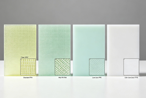
Table of Contents
What Makes a PCB Material Low Loss?
Signal loss in a PCB originates from several sources, including conductor loss, surface roughness, connector transitions, and dielectric loss.
Among these factors, dielectric loss is directly influenced by the laminate material itself.
A material is generally considered low loss when it offers:
- Low dissipation factor (Df)
- Stable dielectric constant (Dk)
- Consistent electrical performance across frequency ranges
- Reduced insertion loss
As explained in Dk and Df Values in PCB Materials, dissipation factor is one of the primary indicators used to evaluate signal loss performance.
Why Standard FR4 Has Limitations
FR4 remains the most widely used PCB material because it is cost-effective and readily available.
However, its electrical performance becomes less favorable as frequencies and data rates increase.
Typical FR4 characteristics include:
- Dk: 4.2–4.8
- Df: 0.015–0.025
For many industrial and consumer products, these values are perfectly acceptable.
However, applications such as:
- 25G Ethernet
- 56G PAM4
- 112G backplanes
- High-speed server platforms
often require lower dielectric loss than conventional FR4 can provide.
Readers new to FR4 materials may refer to FR4 PCB Material Explained for additional background.
Characteristics of Low Loss Materials
Low loss laminates are engineered to improve signal transmission performance.
Common characteristics include:
Lower Dissipation Factor
The most significant advantage is reduced dielectric loss.
Lower Df values help:
- Minimize attenuation
- Improve eye diagrams
- Extend routing distances
- Reduce equalization requirements
Stable Dielectric Constant
Low loss materials often maintain more consistent Dk values across wider frequency ranges.
This improves:
- Impedance control
- Signal timing
- Differential pair matching
Improved High-Frequency Performance
Many low loss systems are optimized for frequencies where standard FR4 begins to experience significant attenuation.
Better Reliability
Premium laminate systems often offer enhanced thermal and mechanical performance as well.
Typical Df Comparison
The following table illustrates how common PCB materials compare.
| Material | Typical Df |
|---|---|
| Standard FR4 | 0.015–0.025 |
| High TG FR4 | 0.012–0.020 |
| Low Loss FR4 | 0.006–0.010 |
| Megtron 6 | ~0.002 |
| Rogers 4350B | ~0.0037 |
| PTFE Materials | 0.0009–0.002 |
The lower the Df value, the lower the dielectric loss.
However, material selection should always consider overall design requirements rather than focusing on a single specification.
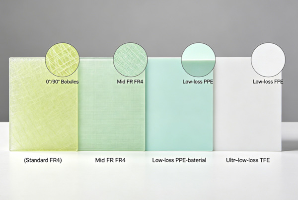
Common Types of Low Loss PCB Materials
Enhanced FR4 Systems
Many laminate suppliers offer improved FR4 formulations designed for higher-speed applications.
These materials provide:
- Better signal performance
- Familiar processing characteristics
- Lower cost compared with premium RF laminates
They are often used in networking and server products.
Hydrocarbon Ceramic Materials
These laminates combine hydrocarbon resin systems with ceramic fillers.
Benefits include:
- Lower loss
- Stable dielectric properties
- Good manufacturability
Several popular RF materials use this approach.
PTFE-Based Materials
PTFE offers some of the lowest dielectric losses available in PCB manufacturing.
Applications include:
- Radar systems
- Satellite communication
- RF amplifiers
- Microwave circuits
A dedicated article on PTFE PCB Material will explore these materials in more detail.
High-Speed Digital Laminates
Products such as:
- Megtron series
- Isola I-Speed
- Tachyon
- Nelco high-speed materials
are specifically designed for modern digital systems.
These materials bridge the gap between conventional FR4 and specialized RF substrates.
Applications That Benefit from Low Loss Materials
Data Center Equipment
Modern switches and routers operate at increasingly high data rates.
Signal loss becomes a critical design factor as channel lengths increase.
Low loss materials help maintain signal quality throughout the system.
Future coverage will include PCB Materials for Data Center Equipment.
AI Servers
AI infrastructure requires high-speed communication between processors, accelerators, and memory devices.
Low loss laminates help support:
- High bandwidth
- Reduced latency
- Improved signal integrity
Telecommunication Systems
Applications include:
- Optical networking
- 5G infrastructure
- Backhaul equipment
- Wireless communication hardware
High-Speed Storage Systems
Enterprise storage platforms often rely on low loss materials to support high-speed interfaces and long signal paths.
Cost Considerations
One reason standard FR4 remains popular is cost.
Low loss materials generally increase PCB fabrication expenses due to:
- Higher laminate pricing
- More complex stackup requirements
- Additional engineering effort
The performance benefits must justify the additional cost.
In many cases, only specific layers require low loss materials, allowing designers to use hybrid stackups that balance performance and budget.
Low Loss Materials and Stackup Design
Material selection cannot be separated from stackup planning.
Factors that should be evaluated together include:
- Layer count
- Core thickness
- Prepreg selection
- Copper roughness
- Target impedance
As discussed in PCB Core and Prepreg Materials, dielectric spacing directly influences impedance and signal behavior.
A well-designed stackup often contributes as much to performance as the material itself.
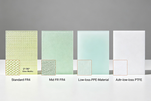
Choosing the Right Material
When evaluating low loss laminates, engineers should consider:
Data Rate
Higher data rates generally increase the importance of low dielectric loss.
Operating Frequency
RF and microwave designs often require specialized materials.
Channel Length
Longer signal paths typically benefit more from low loss materials.
Manufacturing Requirements
Some materials require specialized drilling, lamination, or handling processes.
Budget
Material selection should align with product performance targets and market expectations.
The goal is not to choose the lowest-loss material available, but the most appropriate material for the application.
FAQ
A: A low loss PCB material is a laminate designed to reduce dielectric attenuation and improve signal integrity at high frequencies or high data rates.
A: They help minimize signal degradation, allowing signals to travel longer distances with better quality.
A: Not always. Some low loss materials are designed for high-speed digital systems rather than RF applications.
A: In some cases, yes. However, very high data rates often require materials with lower dielectric loss.
A: Networking, telecommunications, AI computing, data centers, aerospace, and advanced industrial electronics frequently use low loss PCB materials.