Material selection becomes increasingly important as operating frequencies move beyond the capabilities of conventional PCB designs. In RF, microwave, millimeter-wave, and high-speed communication systems, the electrical properties of the laminate can directly affect signal loss, impedance stability, insertion loss, and overall system performance.
While standard FR4 remains suitable for many electronic products, high-frequency circuits often require materials specifically engineered to maintain consistent electrical characteristics across wider frequency ranges.
Choosing the right material early in the design phase can help avoid signal integrity issues, redesign costs, and manufacturing challenges later in the project.
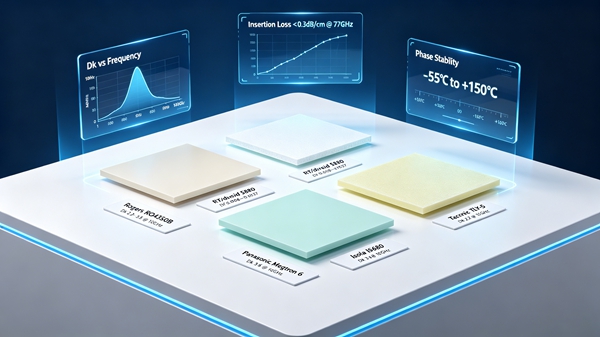
Table of Contents
Why Material Selection Matters at High Frequencies
At lower frequencies, PCB performance is primarily influenced by circuit layout and component selection.
As frequency increases, material properties become increasingly significant.
Several factors contribute to this shift:
- Increased dielectric loss
- Greater insertion loss
- Higher sensitivity to impedance variation
- More demanding signal integrity requirements
Materials that perform well in low-speed digital applications may not deliver acceptable results in RF or high-speed communication systems.
This is one reason why material selection has become a critical part of modern PCB engineering.
The Most Important Material Properties
Dielectric Constant (Dk)
Dk influences signal velocity and impedance.
A stable dielectric constant helps maintain predictable electrical performance across different frequencies.
As explained in Dk and Df Values in PCB Materials, even small variations in Dk can affect impedance-controlled structures.
Dissipation Factor (Df)
Df determines how much signal energy is lost within the dielectric material.
Lower Df values generally result in:
- Reduced insertion loss
- Improved signal quality
- Longer transmission distances
For many high-frequency designs, Df becomes one of the most important material parameters.
Thermal Stability
Communication equipment often operates continuously in demanding environments.
Thermal stability helps ensure:
- Consistent electrical performance
- Reduced mechanical stress
- Improved long-term reliability
Moisture Resistance
Moisture absorption can alter dielectric properties and affect RF performance.
Materials designed for high-frequency applications typically exhibit low moisture absorption characteristics.
Can FR4 Be Used for High-Frequency PCBs?
The answer depends on the operating frequency and performance requirements.
Standard FR4 performs well in:
- Consumer electronics
- Industrial control products
- General communication equipment
Many designs operating below several gigahertz can successfully use FR4 without significant issues.
For a detailed discussion of conventional laminate performance, see FR4 PCB Material Explained.
However, as frequencies increase, the relatively high dielectric loss of FR4 becomes a limitation.
Engineers often transition to low-loss or RF-specific materials when:
- Signal loss becomes excessive
- Channel lengths increase
- RF performance requirements become stricter
High TG FR4 in Communication Equipment
High TG materials are frequently selected for communication products due to their thermal reliability.
Advantages include:
- Better dimensional stability
- Improved resistance to thermal cycling
- Enhanced manufacturing reliability
However, high TG FR4 should not automatically be considered a high-frequency material.
Its primary advantage is thermal performance rather than significantly lower signal loss.
Additional information can be found in High TG FR4 PCB.
Low Loss Materials for High-Speed Digital Designs
Many modern networking and computing products use low-loss laminate systems rather than traditional RF materials.
Typical applications include:
- Data center switches
- AI servers
- High-speed storage systems
- Telecommunications infrastructure
These materials offer:
- Lower Df values
- Better signal integrity
- Improved channel performance
Compared with RF laminates, they often provide a more practical balance between performance and cost.
Readers interested in this category may refer to Low Loss PCB Materials Explained.
Rogers Materials
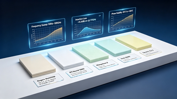
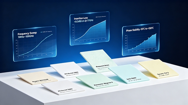
Rogers laminates are among the most widely recognized materials used in RF and microwave PCB fabrication.
Common product families include:
- Rogers 4350B
- Rogers 4003C
- Rogers 5880
Advantages include:
- Stable Dk values
- Low dielectric loss
- Excellent high-frequency performance
- Good process stability
Applications include:
- Radar systems
- RF amplifiers
- Antenna circuits
- Satellite communication equipment
Future articles will examine specific Rogers materials in greater detail.
PTFE-Based Materials
PTFE remains one of the lowest-loss dielectric systems available for PCB manufacturing.
Characteristics include:
- Extremely low Df
- Excellent RF performance
- Stable electrical behavior
PTFE materials are commonly found in:
- Microwave systems
- Aerospace electronics
- Military communication equipment
- High-frequency test equipment
Although performance is excellent, PTFE materials typically require more specialized processing compared with FR4-based laminates.
Megtron and High-Speed Digital Materials
The growth of cloud computing and AI infrastructure has increased demand for advanced high-speed laminates.
Materials such as:
- Megtron 6
- Megtron 7
- Isola I-Speed
- Tachyon
- Nelco high-speed systems
have become increasingly common in:
- Data center hardware
- AI servers
- Networking platforms
- High-performance computing systems
These materials are optimized for digital signal integrity rather than purely RF applications.
Material Selection by Application
Different applications often require different material strategies.
Consumer Electronics
Typical material:
- Standard FR4
Primary consideration:
- Cost efficiency
Industrial Control Systems
Typical material:
- FR4
- High TG FR4
Primary consideration:
- Reliability
High-Speed Networking
Typical material:
- Low-loss laminates
- Megtron
- Isola high-speed materials
Primary consideration:
- Signal integrity
RF and Microwave Systems
Typical material:
- Rogers
- PTFE
- Taconic
Primary consideration:
- Low dielectric loss
Aerospace and Defense
Typical material:
- PTFE
- Advanced RF laminates
- Hybrid material stackups
Primary consideration:
- Performance under demanding operating conditions
Hybrid Material Stackups
Not every design requires a single laminate system throughout the entire PCB.
Many advanced products use hybrid stackups that combine:
- FR4
- Low-loss materials
- Rogers laminates
Benefits include:
- Reduced material costs
- Improved manufacturability
- Optimized electrical performance
Hybrid constructions are especially common in RF products that contain both digital and microwave circuitry.
Common Material Selection Mistakes
Focusing Only on Dk
Dk is important, but Df, thermal performance, and manufacturability must also be considered.
Choosing the Lowest-Loss Material Available
The most expensive material does not automatically provide the best overall solution.
Ignoring Manufacturing Requirements
Certain materials require specialized drilling, lamination, and handling processes.
Over-Specifying Materials
Many designs can achieve their goals using low-loss laminates without requiring premium RF substrates.
FAQ
A: The best material depends on the application. Rogers, PTFE, and low-loss laminates are among the most commonly used options.
A: Yes, for some lower-frequency RF applications. Higher frequencies often require materials with lower dielectric loss.
A: Df directly affects insertion loss and signal attenuation, making it critical for RF and high-speed circuits.
A: Many 5G products use Rogers, PTFE, or advanced low-loss laminates depending on operating frequency and performance requirements.
A: Not always. Material selection should be based on data rate, channel length, signal integrity requirements, and overall project cost.