PTFE is one of the most widely used dielectric materials for high-frequency and microwave PCBs. Thanks to its exceptionally low dielectric loss and stable electrical properties, it has become a preferred choice for RF communication, radar systems, satellite electronics, aerospace, and advanced test equipment.
Compared with standard FR4, PTFE offers significantly better signal transmission performance at high frequencies. However, these electrical advantages also introduce additional manufacturing challenges that designers should consider during material selection.
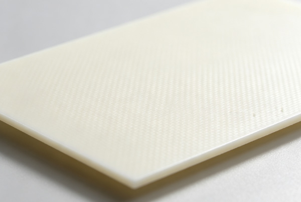
Table of Contents
What Is PTFE?
PTFE stands for Polytetrafluoroethylene, a synthetic fluoropolymer known for its excellent electrical insulation and chemical stability.
Unlike epoxy-based laminates such as FR4, PTFE materials maintain very stable dielectric properties over a wide frequency range.
In PCB manufacturing, PTFE is often reinforced with:
- Glass fiber
- Ceramic fillers
- Woven fiberglass
These reinforcement materials improve mechanical strength while maintaining the excellent electrical performance that PTFE is known for.
As discussed in PCB Laminate Materials Explained, PTFE belongs to the family of specialty laminates designed for demanding electrical applications.
Why PTFE Is Used in High-Frequency PCBs
As operating frequencies increase, dielectric loss becomes one of the primary factors affecting signal quality.
PTFE offers several advantages over conventional laminate materials.
Extremely Low Dielectric Loss
One of PTFE’s biggest advantages is its very low dissipation factor.
Typical values include:
- Dk: 2.1–2.6
- Df: 0.0009–0.002
Compared with FR4, signal attenuation is significantly lower.
This allows signals to travel longer distances while maintaining better integrity.
The relationship between Dk and Df is explained in more detail in Dk and Df Values in PCB Materials.
Stable Dielectric Constant
PTFE materials maintain relatively stable dielectric properties across broad frequency ranges.
This benefits:
- Controlled impedance
- Phase matching
- RF filter performance
- Antenna consistency
Low Moisture Absorption
Moisture has very little effect on PTFE.
This makes it suitable for outdoor communication equipment and harsh operating environments.
PTFE Compared with FR4
The differences between PTFE and FR4 become more apparent as frequency increases.
| Property | FR4 | PTFE |
|---|---|---|
| Dielectric Constant | 4.2–4.8 | 2.1–2.6 |
| Dissipation Factor | 0.015–0.025 | 0.0009–0.002 |
| RF Performance | Moderate | Excellent |
| Material Cost | Lower | Higher |
| Manufacturing Difficulty | Lower | Higher |
For general-purpose electronics, FR4 remains the most economical choice.
Readers unfamiliar with conventional laminate materials may find FR4 PCB Material Explained useful before evaluating specialty materials.
Common PTFE PCB Applications
PTFE materials are widely used in industries where signal quality cannot be compromised.
RF Communication Equipment
Applications include:
- RF amplifiers
- Wireless modules
- RF filters
- Duplexers
Radar Systems
Automotive and defense radar systems frequently use PTFE laminates because of their low dielectric loss.
Satellite Communications
Satellite equipment benefits from:
- Stable electrical performance
- Low insertion loss
- Reliable operation over wide temperature ranges
Aerospace Electronics
PTFE is commonly found in avionics, navigation systems, and airborne communication equipment.
Test and Measurement Equipment
Precision RF instruments often require extremely stable dielectric performance.
PTFE Manufacturing Challenges
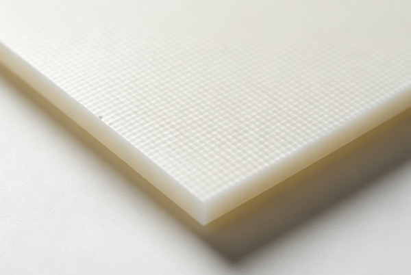
Although PTFE offers excellent electrical properties, it is considerably more difficult to process than FR4.
Soft Material Structure
PTFE is mechanically softer than epoxy laminates.
Special handling procedures are often required during drilling and routing.
Higher Thermal Expansion
PTFE exhibits a higher coefficient of thermal expansion.
Proper stackup design is important to reduce mechanical stress during assembly.
Lamination Process
PTFE materials require carefully controlled lamination parameters.
Temperature, pressure, and bonding materials must all be considered.
Designers working with multilayer RF boards should also understand how PCB Core and Prepreg Materials influence overall stackup performance.
PTFE and Hybrid PCB Stackups
Not every PCB requires a fully PTFE construction.
Many RF products combine:
- PTFE signal layers
- FR4 core materials
- Standard prepregs
Hybrid stackups provide several advantages:
- Lower material costs
- Easier fabrication
- Improved mechanical stability
This approach has become common in communication equipment where only selected layers operate at very high frequencies.
PTFE Compared with Rogers Materials
PTFE and Rogers materials are often mentioned together, but they are not identical.
Many Rogers laminate families use hydrocarbon ceramic systems rather than pure PTFE.
Generally speaking:
- PTFE provides the lowest dielectric loss.
- Rogers materials often offer easier processing.
- Both are widely used in RF PCB manufacturing.
Readers interested in Rogers laminates can continue with Rogers PCB Material for a broader comparison.
Is PTFE Always the Best Choice?
Not necessarily.
For many networking and high-speed digital products, modern low-loss laminates deliver excellent performance without the additional manufacturing complexity associated with PTFE.
As explained in Low Loss PCB Materials Explained, material selection should balance electrical performance, manufacturing capability, and project cost.
Choosing PTFE solely because it has the lowest Df value may increase production costs without delivering meaningful benefits in every application.
FAQ
A: PTFE is a fluoropolymer-based laminate widely used in RF, microwave, and high-frequency PCB applications because of its extremely low dielectric loss.
A: Its low dielectric constant and very low dissipation factor help reduce signal loss and improve high-frequency performance.
A: For RF and microwave circuits, PTFE generally provides better electrical performance. For standard electronics, FR4 is often more economical.
A: Yes. PTFE requires specialized drilling, lamination, and fabrication processes compared with conventional FR4 materials.
A: Yes. Hybrid stackups using PTFE and FR4 are common in communication and RF products where only certain layers require premium dielectric performance.